Proximity switch sensors are essential components in modern industrial automation, providing non-contact detection of metallic or non-metallic objects. Understanding their wiring is crucial for ensuring reliable operation and system integration. This guide offers a comprehensive overview of proximity sensor wiring diagrams, covering common types, terminal functions, and practical installation tips.
Proximity sensors are typically categorized into three main types based on their output configurations: two-wire, three-wire, and four-wire sensors. Each type has distinct wiring requirements that must be followed to avoid malfunctions or damage.
Two-wire proximity sensors are the simplest in design, consisting of only two wires for both power supply and load connection. They are directly connected in series with the load, making installation straightforward. However, they may have higher residual current and voltage drop compared to other types. When wiring a two-wire sensor, ensure the power supply voltage matches the sensor's specifications, typically ranging from 10-30V DC or 20-250V AC. The load (such as a relay or PLC input) is connected in series, and polarity is not a concern for AC models, while DC models require correct positive and negative connections.
Three-wire proximity sensors are the most common in industrial applications due to their reliability and performance. They feature three terminals: brown (positive), blue (negative), and black (output). The brown wire connects to the positive DC supply voltage, usually 10-30V DC. The blue wire is linked to the negative or ground terminal. The black wire serves as the output signal, which can be either NPN (sinking) or PNP (sourcing). In NPN configurations, the output switches the negative side of the load, whereas PNP switches the positive side. Always verify the sensor's datasheet to confirm the output type before wiring. For example, in a typical NPN setup, the load is connected between the positive supply and the black wire, completing the circuit when the sensor detects an object.
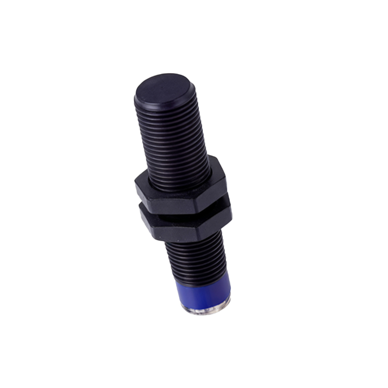
Four-wire proximity sensors include two output wires, often allowing both normally open (NO) and normally closed (NC) contacts. These sensors provide flexibility for control logic, with wires typically colored brown (positive), blue (negative), black (NO output), and white (NC output). Wiring follows similar principles to three-wire sensors, with careful attention to selecting the appropriate output based on the application requirements.
Key considerations for wiring include using shielded cables to reduce electromagnetic interference, especially in environments with motors or frequency drives. Maintain proper cable lengths as specified by the manufacturer to prevent signal degradation. Always disconnect power before making connections to avoid short circuits or electric shock. Additionally, ensure the sensor is mounted correctly with adequate clearance from metal surfaces to prevent false triggering.
For integrating proximity sensors with programmable logic controllers (PLCs), match the sensor output type with the PLC input specifications. NPN sensors are compatible with sinking PLC inputs, while PNP sensors work with sourcing inputs. Incorrect pairing can lead to communication failures. In complex systems, refer to the control panel layout and wiring diagrams provided by equipment manufacturers for precise guidance.
Troubleshooting common wiring issues involves checking voltage levels, verifying connections against the diagram, and inspecting for loose or corroded terminals. Use a multimeter to measure output signals during activation. If the sensor fails to operate, confirm the power supply, load compatibility, and environmental factors such as temperature or contamination.
In summary, proper wiring of proximity switch sensors is fundamental to automation system performance. By adhering to standardized diagrams and best practices, engineers can ensure accurate detection, enhanced safety, and reduced downtime. Always consult the specific sensor manual for detailed instructions tailored to the model in use.