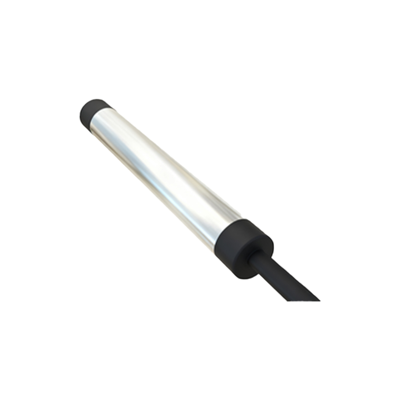
In the realm of industrial automation, proximity sensors are indispensable components for non-contact detection of metallic objects. Among the various configurations, the 3-wire DC proximity sensor stands out as the most prevalent and versatile solution for countless applications. This article delves into the technical intricacies, wiring methodologies, operational principles, and key selection criteria for these critical devices, providing a comprehensive guide for engineers and technicians.
At its core, a 3-wire DC proximity sensor is a solid-state electronic device designed to detect the presence or absence of a target without physical contact. It operates on a DC power supply, typically ranging from 10 to 30 VDC. The "3-wire" designation refers to its connection terminals: one for DC positive (brown wire), one for DC negative or common (blue wire), and one for the output signal (black wire). This configuration separates the power supply lines from the output switching line, offering significant advantages in noise immunity and circuit design flexibility compared to 2-wire versions.
The operation hinges on an oscillator circuit that generates a high-frequency electromagnetic field at the sensor's active face. When a metallic target enters this field, eddy currents are induced in the target, causing a change in the oscillation amplitude. This change is detected by a threshold circuit, which subsequently triggers the solid-state output switch. For DC sensors, the output is either a switching transistor configured as a sink (NPN) or a source (PNP). An NPN sensor switches the negative (common) line to the load, while a PNP sensor switches the positive line. Understanding this distinction is paramount for correct integration into control systems, such as PLCs (Programmable Logic Controllers).
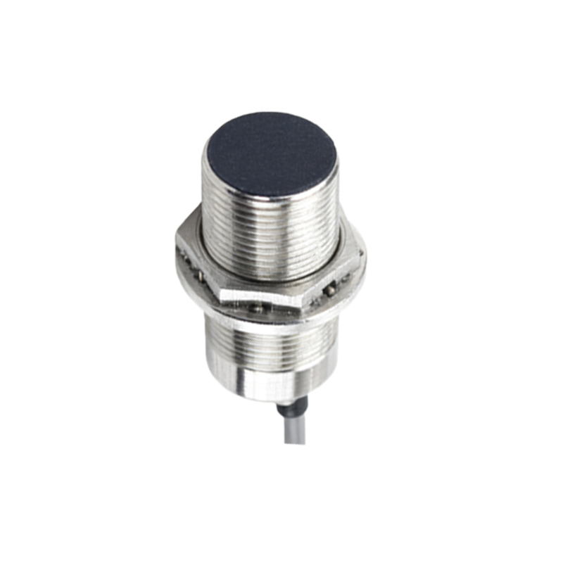
Wiring a 3-wire DC sensor is a straightforward but precise task. Always begin by consulting the manufacturer's datasheet for the specific pinout and voltage ratings. The standard color coding (brown: +V, blue: 0V/common, black: output) is widely adopted but not universal. For a typical NPN normally-open (NO) sensor: connect the brown wire to the positive DC supply, the blue wire to the negative/ground of the supply, and the black output wire to one terminal of the load (e.g., a PLC input). The other terminal of the load is then connected to the positive supply. This creates a circuit where the sensor's internal transistor, when activated, completes the path to ground for the load. For a PNP NO sensor, the black output wire connects to the load, and the other side of the load connects to the negative/ground. The power wiring (brown and blue) remains identical. A critical best practice is to implement proper shielding and routing of cables away from high-voltage power lines to prevent electromagnetic interference. Additionally, incorporating a protective fuse or circuit breaker in the supply line is highly recommended.
Selecting the appropriate 3-wire proximity sensor requires careful consideration of several application-specific parameters. First, define the sensing distance or "rated operating distance (Sn)." This is the nominal range at which a standard target will reliably trigger the sensor. Never design for operation at the absolute maximum; a safety factor of 60-70% of Sn is advisable. Next, determine the required output type: NPN or PNP, and switching logic (normally-open or normally-closed). This choice is dictated by the input module of your controller. The target material is another key factor; while ferrous metals (like mild steel) offer the longest sensing ranges, sensors can be calibrated for non-ferrous metals (aluminum, copper) or stainless steel, often with a reduced range. Environmental conditions cannot be overlooked. Consider the sensor's housing material (e.g., nickel-plated brass, stainless steel), ingress protection (IP) rating for dust and water resistance, and temperature range. For harsh environments involving washdowns or chemicals, sensors with high IP ratings (IP67, IP69K) and stainless steel housings are essential.
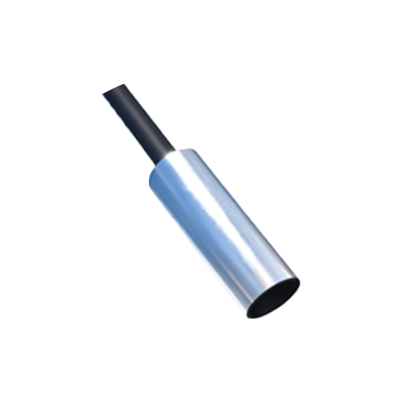
Finally, understanding the electrical characteristics is crucial for reliable operation. Pay close attention to the supply voltage range, current consumption, and the output's maximum switching current and voltage drop. Ensure the sensor's residual current (leakage current when "off") is low enough not to falsely trigger your PLC input. Also, note the switching frequency, which defines how quickly the sensor can detect passing targets, a vital spec for high-speed counting or sorting applications.
In conclusion, the 3-wire DC proximity sensor is a robust, reliable, and flexible workhorse of industrial sensing. Its three-wire design offers superior performance and easier integration into modern DC control systems. By mastering its wiring conventions, operational logic, and selection parameters—encompassing sensing distance, output configuration, target material, and environmental robustness—engineers can ensure optimal