In the realm of industrial automation and machine control, proximity sensors are indispensable components for non-contact detection of metallic or non-metallic objects. Among the various configurations, the 3-wire proximity sensor is arguably the most common and versatile type found on factory floors worldwide. Understanding its wiring diagram is fundamental for any engineer, technician, or maintenance professional involved in system design, installation, and troubleshooting. This article delves into the intricacies of the 3-wire proximity sensor circuit, explaining its operation, standard wiring practices, and key considerations for reliable implementation.
At its core, a 3-wire proximity sensor is an active electronic device that requires a DC power supply to operate. The three wires are distinctly color-coded according to international standards, typically brown, blue, and black. The brown wire is universally designated for the positive DC supply voltage (+V), while the blue wire is for the common negative or 0V (DC common). The third wire, most often black, is the signal output line. This output can be either a PNP (sourcing) or NPN (sinking) transistor configuration, which dictates how the sensor interfaces with the programmable logic controller (PLC) or other control circuitry.
The internal circuit of a 3-wire sensor integrates an oscillator, a detection circuit, an amplifier, and a solid-state output switch (the transistor). When powered, the oscillator generates a high-frequency electromagnetic field at the sensor's active face. The presence of a target within its sensing range induces eddy currents (for metallic targets) or changes the field characteristics, which is detected by the sensing circuit. This change triggers the amplifier, which in turn commands the output transistor to change state.
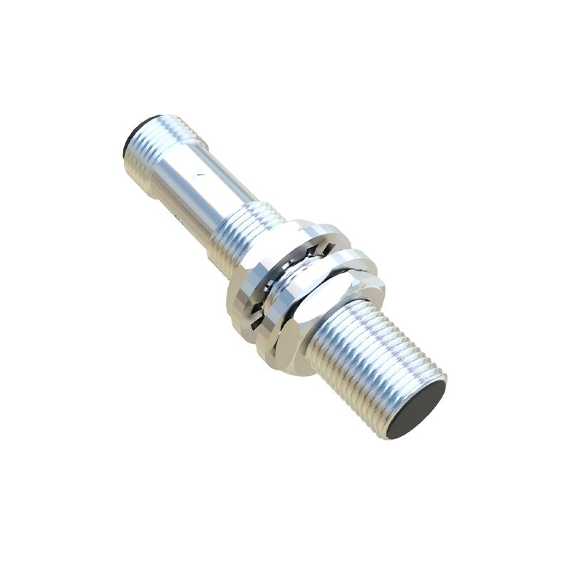
For a PNP-type sensor, the black output wire is connected to the collector of a PNP transistor inside the sensor. When the sensor detects an object, the transistor switches "ON," connecting the black wire internally to the positive supply (brown wire). Thus, it sources current from the sensor to the load. The standard wiring is: Brown (+V) to the positive DC supply (e.g., +24VDC), Blue to the 0V/DC common, and Black to the input of the PLC. The PLC input's common terminal is then connected to the 0V supply. In this configuration, the sensor provides a positive voltage signal to the PLC upon detection.
Conversely, an NPN-type sensor has an NPN transistor. Its black output wire is connected to the transistor's collector. When activated, the transistor switches "ON," connecting the black wire internally to the negative supply (blue wire). It sinks current from the load into the sensor. The wiring is similar: Brown (+V) and Blue (0V) to the power supply. However, the black wire is connected to the PLC input, and the common terminal of that PLC input module must be connected to the positive supply (+V). Here, the sensor pulls the PLC input to 0V when an object is detected.
A critical aspect of the wiring diagram is the inclusion of a load, which is typically the input channel of a PLC, a relay coil, or an indicator lamp. This load must be connected in series with the sensor's output (black wire) and the appropriate power rail, depending on the type (PNP or NPN). Furthermore, for DC sensors, attention must be paid to polarity; reversing the brown and blue wires will permanently damage the device. Most quality sensors incorporate reverse polarity protection, but it remains a fundamental rule.
Another vital component often shown in detailed wiring diagrams is a protective circuit or suppressor. Inductive loads like relay coils can generate voltage spikes when de-energized. To protect the sensor's fragile transistor output, a free-wheeling diode (for DC loads) or a Metal-Oxide Varistor (MOV) is frequently wired in parallel with the load. For DC circuits, the diode is installed with the cathode to the positive side, providing a safe path for the reverse current.
Selecting between PNP and NPN is primarily determined by the control system's architecture. European-designed systems traditionally favor PNP (positive logic), while Asian-designed systems often use NPN (negative logic). Modern PLCs with universal inputs can typically accept either type, but the common terminal wiring must be adjusted accordingly, as described. Mis-matching the sensor type and PLC input configuration is a common installation error that results in the sensor failing to trigger the controller.
In conclusion, the 3-wire proximity sensor's wiring diagram is a blueprint for reliable, noise-immune signal acquisition. Mastery of the PNP vs. NPN distinction, strict adherence to color codes and polarity, and the proper integration of protective elements are non-negotiable for ensuring upt