Disassembling a laser sensor requires precision, caution, and a clear understanding of its internal components. Whether for maintenance, repair, or component analysis, following a systematic approach is crucial to avoid damage to sensitive optical and electronic parts. This guide provides detailed instructions tailored for engineers and technicians in the electrical and automation industries.
Before beginning any disassembly, ensure you have the necessary tools: anti-static wrist straps, precision screwdrivers (including Torx and Phillips heads), tweezers, a clean, static-free work surface, and appropriate containers for small screws and components. Always consult the sensor's specific technical manual or datasheet, as designs vary significantly between manufacturers and models.
Step 1: Power Disconnection and Safety Precautions
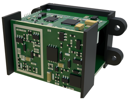
First, completely disconnect the laser sensor from all power sources and connected cables. This includes unplugging it from the control system and removing any backup batteries if present. Allow the sensor to sit for at least 15 minutes to let any residual electrical charge dissipate. Wear an anti-static wrist strap throughout the process to prevent electrostatic discharge (ESD) damage to internal circuits.
Step 2: External Casing Removal
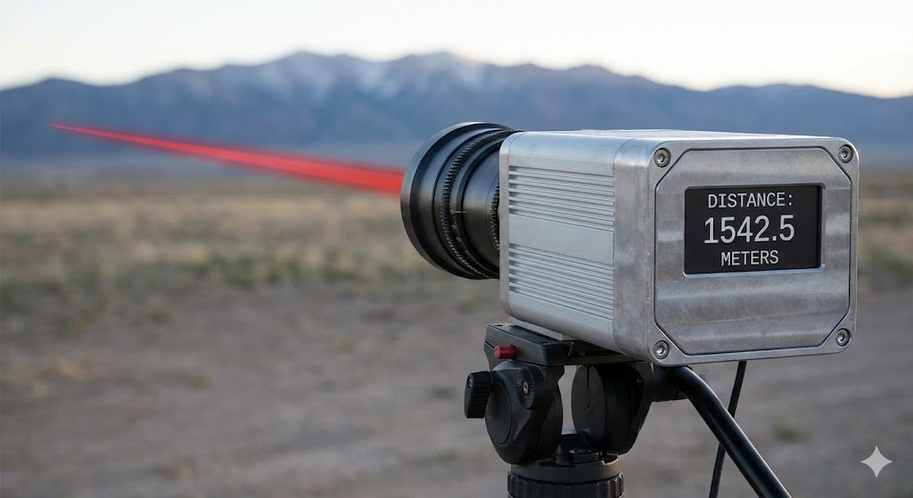
Most laser sensors feature a main housing secured by small screws, often hidden under labels or rubber seals. Carefully remove any visible screws using the correct screwdriver size to avoid stripping the heads. Some casings may use clips or snap-fit designs; gently pry these open with a non-conductive spudger tool, working evenly around the edges. Keep all screws organized.
Step 3: Accessing Internal Modules
Once the outer casing is removed, you will typically see the internal assembly, which may include a main PCB (printed circuit board), the laser diode module, receiver optics (like a photodiode or CCD), and various connectors. Do not immediately pull components apart. First, document the layout with photos or sketches, noting cable orientations and connector types.
Step 4: Disconnecting Internal Cables and Connectors
Internal connections are often delicate. Identify any ribbon cables, ZIF (Zero Insertion Force) connectors, or small wire harnesses. For ribbon cables, gently lift the locking flap on the ZIF connector before sliding the cable out. For wire harnesses, note their positions and carefully unclip or unscrew terminal blocks. Avoid pulling on wires directly.
Step 5: Removing the Laser Diode and Optical Assembly
The laser emitter and receiver optics are the core of the sensor. They are usually mounted on separate sub-assemblies or directly on the main PCB. Look for mounting screws or adhesive pads securing these modules. Before removal, note the alignment—optical components often have precise positioning that must be replicated during reassembly. Use tweezers for small screws, and handle optical surfaces only by their edges to prevent contamination.
Step 6: PCB Extraction and Further Disassembly
If necessary, the main PCB can be removed by unscrewing its standoffs. Be mindful of any ground straps or thermal pads attached. At this stage, individual components like ICs, resistors, or the laser driver circuit are exposed. However, unless specifically required, avoid desoldering components, as this can permanently damage the board.
Critical Considerations During Disassembly:
- Laser Safety: Even when powered off, avoid direct eye exposure to the laser diode aperture. Treat it as potentially active.
- Cleanliness: Work in a dust-free environment. Use compressed air or a soft brush to remove debris, but never touch optical lenses directly.
- Static Control: Continuously use ESD protection. Place removed components on anti-static mats.
- Documentation: Meticulous notes and photos are essential for correct reassembly. Sensor calibration can be affected by misaligned components.
Reassembly Notes:
Reassembly is essentially the reverse process. Ensure all connectors are firmly seated, screws are tightened to the specified torque (if provided), and optical alignments match your documentation. After reassembly, perform basic functional tests in a controlled setting before reintegrating the sensor into a live system.
Remember, disassembly may void manufacturer warranties and should only be undertaken by qualified personnel. For complex or high-value sensors, consulting the manufacturer or a certified repair service is often the safest course of action. Proper technique not only preserves the sensor’s functionality but also extends its service life through careful handling.