In the realm of industrial automation and electrical engineering, proximity sensors are indispensable components for detecting the presence or absence of objects without physical contact. Understanding their electrical symbols is crucial for accurate circuit design, schematic interpretation, and system integration. These symbols, standardized by organizations such as the International Electrotechnical Commission (IEC) and the Institute of Electrical and Electronics Engineers (IEEE), provide a universal language for engineers worldwide.
Proximity sensors are broadly categorized based on their detection principles, each represented by distinct symbols. Inductive proximity sensors, designed to detect metallic objects, typically feature a coil icon within a square or diamond-shaped outline, often accompanied by a waveform symbol indicating alternating current operation. Capacitive sensors, capable of sensing both metallic and non-metallic materials, are denoted by parallel plate symbols inside the enclosure, reflecting their principle of measuring capacitance changes. Ultrasonic sensors use sound wave symbols, while photoelectric sensors incorporate light beam and receiver icons. Magnetic sensors (e.g., reed switches) include a magnet symbol.
The basic electrical symbol structure for a proximity sensor consists of an outer shape—usually a square, circle, or diamond—enclosing an inner icon representing the sensing technology. Connection points, labeled as supply voltage (V+), ground (GND), and output signal (OUT), are indicated with terminals. Output types significantly influence the symbol: PNP (sourcing) outputs are marked with an arrow pointing outward from the symbol, whereas NPN (sinking) outputs have an arrow pointing inward. Normally open (NO) and normally closed (NC) contacts are represented by break or make symbols, respectively.
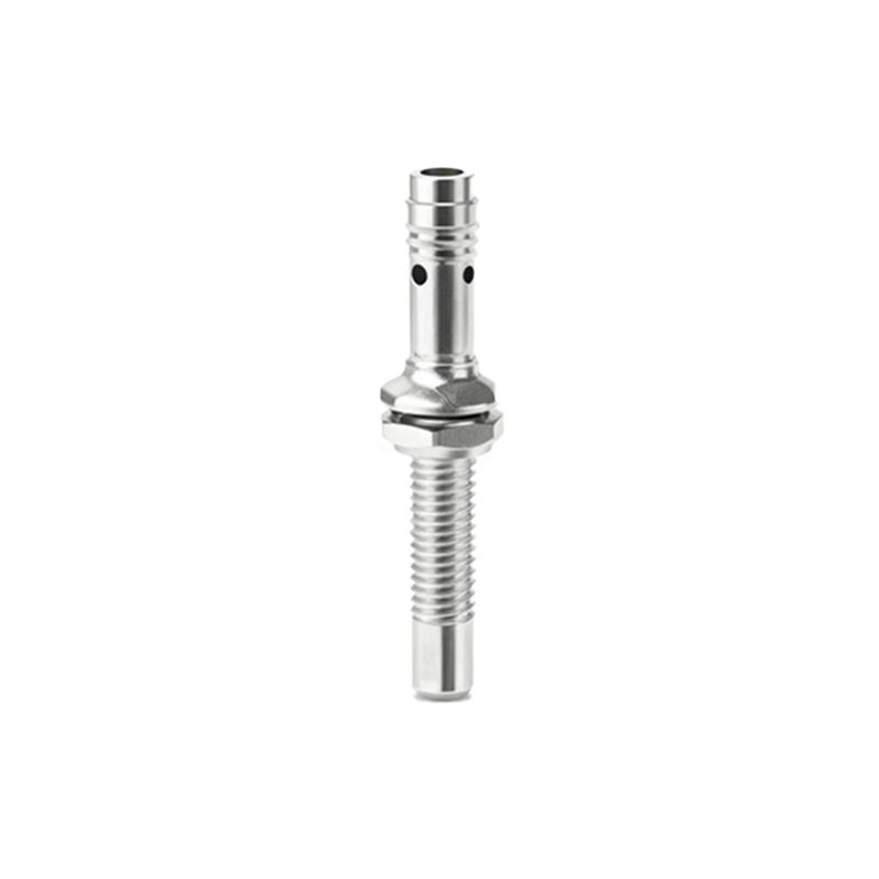
In circuit diagrams, proximity sensor symbols integrate with other components like programmable logic controllers (PLCs), relays, and motors. For instance, an inductive sensor symbol connected to a PLC input module shows how detection triggers control actions. Engineers must also consider supplementary markings for features such as shielding, temperature ratings, or hazardous area certifications (e.g., Ex for explosive environments). Misinterpreting these symbols can lead to wiring errors, operational failures, or safety risks.
Practical applications abound in manufacturing, robotics, and automotive systems. Symbols guide the installation of sensors for position detection, object counting, and safety interlocks. As technology evolves, smart sensors with IO-Link or Ethernet interfaces incorporate additional communication symbols into their representations. Mastery of these symbols enhances design efficiency, troubleshooting speed, and cross-team collaboration, ensuring robust and compliant electrical systems. Always refer to latest standards like IEC 60617 and IEEE 315 for updates, as symbols may adapt to new sensor technologies.