In the rapidly evolving landscape of automotive electronics, proximity switch sensors have become indispensable components, crucial for functions ranging from parking assistance and collision avoidance to automated door systems and gear position detection. As an electrical engineer specializing in automotive systems, understanding the correct wiring methodology for these sensors is paramount for ensuring reliability, safety, and optimal performance. This guide provides a detailed, step-by-step approach to wiring automotive proximity switch sensors, adhering to industry best practices.
Understanding the Core Components
Before commencing any wiring procedure, it is essential to identify the sensor type and its specifications. Automotive proximity sensors are predominantly inductive or capacitive. Inductive sensors detect metallic objects and are commonly used for gear detection or brake pad wear monitoring. Capacitive sensors can detect both metallic and non-metallic objects and are often employed in touch-sensitive controls or liquid level sensing. The datasheet is your primary reference; it details the electrical characteristics, including operating voltage (typically 5V DC, 12V DC, or 24V DC in automotive contexts), current consumption, output type (PNP/NPN, NO/NC), and temperature rating.
A standard three-wire DC sensor is most common:
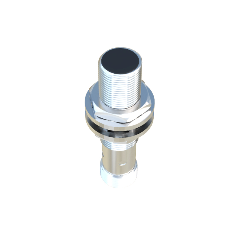
Brown Wire (or Red): Positive Supply Voltage (+V).
Blue Wire (or Black): Negative Supply Voltage (0V or Ground).
Black Wire (or White/Blue): Signal Output.
Essential Pre-Wiring Checklist
1. Power Down: Ensure the vehicle's electrical system is completely de-energized. Disconnect the battery's negative terminal.
2. Review Schematics: Cross-reference the vehicle's wiring diagram and the sensor's datasheet. Confirm pinouts and system logic.
3. Tool Preparation: Use appropriate tools: wire strippers, crimping tools, heat shrink tubing, soldering iron (if required), multimeter, and quality connectors (e.g., Deutsch, AMP, or equivalent automotive-grade).
4. Environment: Work in a clean, dry area. Protect connections from moisture, vibration, and heat, which are prevalent in automotive environments.
Step-by-Step Wiring Procedure
Step 1: Power Supply Connection
The foundation of stable sensor operation is a clean, stable power supply. Identify a suitable power source from the vehicle's fuse box or ECU that matches the sensor's voltage requirement and can handle the inrush and operating current. Using the wiring diagram, connect the sensor's Brown (or Red) wire to this positive supply line. Connect the sensor's Blue (or Black) wire to a solid chassis ground point. Scrape away any paint or corrosion at the ground point to ensure a low-resistance connection. It is highly recommended to fuse the positive supply line close to the power source to protect the circuit.
Step 2: Output Signal Wiring
The output wire carries the switching signal to the control unit (ECU, body control module, etc.). The wiring strategy depends on the output type:
PNP (Sourcing) Output: The sensor switches the positive voltage to the load. The black signal wire is connected to the input channel of the control unit. The control unit's common point is connected to ground.
NPN (Sinking) Output: The sensor switches the ground path to the load. The black signal wire is connected to the control unit input, and the control unit's common point is connected to the positive supply.
Crucially, you must verify whether your control unit is designed for a PNP or NPN input. Mismatching these can lead to malfunction or damage. For a simple indicator light, the load (the light) is placed between the signal wire and the opposite polarity.
Step 3: Shielding and Noise Mitigation
Automotive environments are electrically noisy, with interference from ignition systems, alternators, and motors. For analog output sensors or in high-noise areas, use a shielded cable. Connect the cable's braided shield to ground at one end only (typically at the control unit end) to prevent ground loops. Keep sensor wiring away from high-current cables like battery leads or motor wires. Route them separately or at right angles if they must cross.
Step 4: Connection and Insulation
Always use proper crimp terminals or soldered connections. Avoid "twist-and-tape" methods, as they are unreliable under vibration. After securing the connection, insulate it with adhesive-lined heat shrink tubing. This provides strain relief and environmental sealing superior to electrical tape.
Step 5: Verification and Testing
Before reassembly, conduct thorough tests:
1. Reconnect the battery.
2. Use a multimeter to confirm the supply voltage at the sensor connector is within specification and free of excessive AC ripple.
3.