In industrial automation and control systems, proximity sensors are ubiquitous components for detecting the presence or absence of objects without physical contact. Among the various types, 2-wire and 3-wire DC sensors are most common. While 2-wire sensors are prized for their simplicity and direct compatibility with AC/DC loads, situations often arise where a conversion to a 3-wire configuration becomes necessary. This article delves into the technical rationale, methodology, and critical considerations for converting a 2-wire DC proximity sensor to a 3-wire setup.
Fundamentally, the core difference lies in the wiring scheme. A 2-wire sensor operates in series with the load and the power supply. It functions essentially as a switch, but one that consumes a small leakage current even in its "off" state. This design means there is always a residual voltage drop across the sensor when open, which can sometimes be enough to inadvertently activate a highly sensitive load or PLC input. A 3-wire sensor, in contrast, has separate wires for power supply positive (brown), power supply negative/ground (blue), and the output signal (black). The output transistor (typically PNP or NPN) is internally connected between the signal wire and one of the supply rails, allowing for a much cleaner, full-voltage swing output with minimal residual voltage.
The primary driver for conversion is typically interfacing compatibility. Modern Programmable Logic Controllers (PLCs), microcontrollers, and certain solid-state relays often require a clear, sharp switching signal with a well-defined voltage level close to 0V or the supply voltage. The inherent voltage drop of a 2-wire sensor in the "off" state can cause false triggering or be interpreted as an indeterminate state by these digital inputs. Converting to a 3-wire configuration provides a definitive "dry contact" style signal relative to the common (blue) wire.
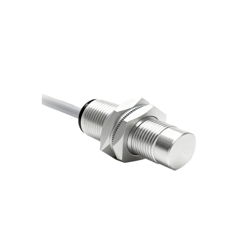
It is crucial to understand that a physical, internal modification of a standard 2-wire sensor to a true 3-wire device is generally not feasible or recommended. The internal circuitry is fundamentally different. Therefore, the "conversion" discussed here is achieved through the use of an external interface module or a carefully designed external circuit. The most reliable and common method is to employ a dedicated signal converter or isolating relay module. These devices are designed to accept the 2-wire sensor's switched loop, internally power the sensor, and provide a clean, isolated 3-wire PNP or NPN output. They effectively act as a buffer, eliminating the leakage current issue and providing a robust signal.
For engineers inclined towards a discrete component solution, an external circuit can be constructed. A typical method involves using the 2-wire sensor to control the base of an external bipolar junction transistor (BJT) or the gate of a MOSFET. The sensor is connected in series with a current-limiting resistor between the positive supply and the transistor's base. The load (e.g., PLC input) is then connected between the transistor's collector (for an NPN) and the positive supply, with the emitter to negative. This arrangement uses the sensor to switch the transistor, which in turn provides a sharp, low-leakage output. However, this approach requires careful calculation of resistor values to ensure the sensor receives enough operating current while properly biasing the transistor. It also introduces additional components and potential points of failure.
Several critical factors must be evaluated before proceeding. First, verify the sensor's operating parameters: its voltage range, nominal operating current, and especially its leakage current in the off state. The external circuit must be designed to ensure the sensor remains within its specified operating current when on. Second, consider the load characteristics. Determine if a PNP (sourcing) or NPN (sinking) output is required for your controller. Third, account for voltage drops. The external transistor or module will have its own saturation voltage, which should be negligible for most applications but must be confirmed. Fourth, isolation and protection are paramount. Ensure the solution provides protection against reverse polarity, short circuits, and voltage transients, especially in harsh industrial environments. Using a commercially available converter module often incorporates these protections.
In summary, while a 2-wire proximity sensor cannot be internally rewired as a 3-wire sensor, its output signal can be effectively adapted to mimic a 3-wire output through external interfacing. The choice between a ready-made signal conditioner and a custom discrete circuit hinges on the application's requirements for reliability, space, cost, and development time. For mission-critical applications, a certified interface module is strongly recommended due to its built-in robustness and safety features. Understanding the underlying electrical principles of both sensor types empowers engineers to select and implement the most reliable and compatible solution for any control system integration challenge.