Proximity sensors, often referred to as proximity switches, are fundamental components in modern industrial automation and control systems. Their ability to detect the presence or absence of an object without physical contact makes them indispensable for tasks ranging from simple object counting to complex robotic positioning. To appreciate their reliability and versatility, it is essential to delve into their internal architecture. While designs vary based on sensing principle—inductive, capacitive, ultrasonic, or photoelectric—this article will focus on the common structural elements, with particular emphasis on the widely used inductive proximity sensor.
At the core of an inductive proximity sensor lies an oscillator circuit. This circuit generates a high-frequency electromagnetic field that radiates from the sensor's active face, typically made of a ferrite core surrounded by a coil. When a metallic target enters this oscillating field, eddy currents are induced on the target's surface. These eddy currents draw energy from the oscillator, causing a reduction in its amplitude. This amplitude change is the primary detection signal.
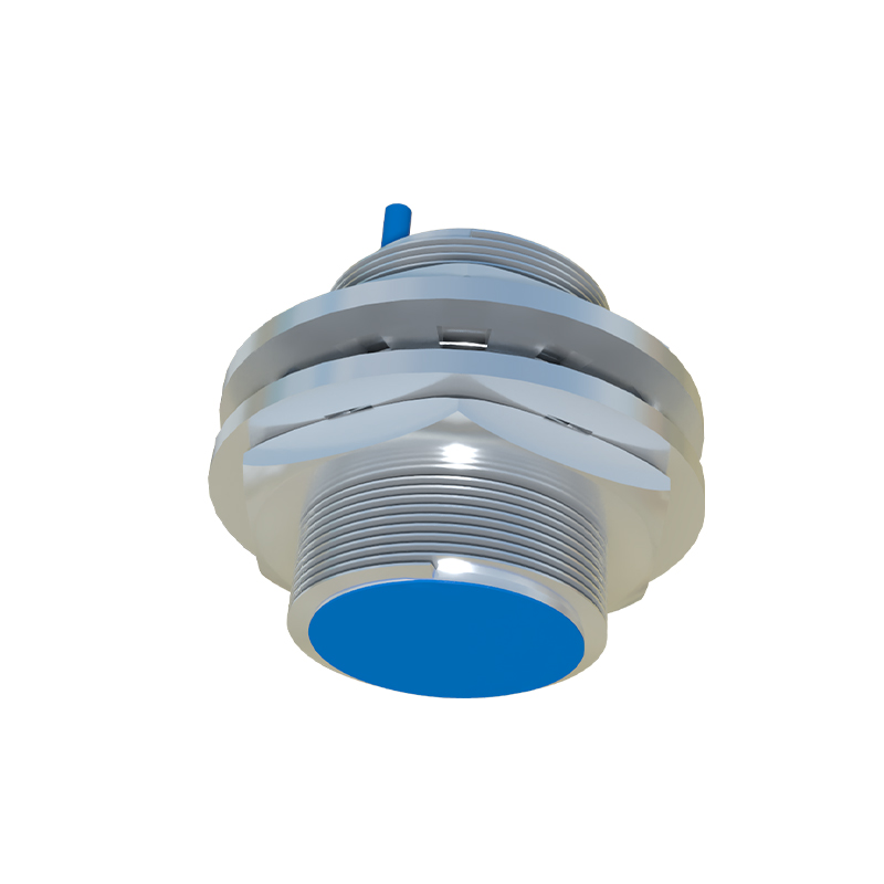
The internal structure is meticulously housed within a robust casing, usually constructed from nickel-plated brass, stainless steel, or engineering plastics like PBT, chosen for mechanical strength and environmental resistance. The key internal components, arranged sequentially from the sensing face inward, include:
1. Sensing Face / Ferrite Core: This is the front-most element. The ferrite core concentrates the electromagnetic field emitted by the oscillator coil, defining the sensor's sensing range and directionality. It is often protected by a wear-resistant epoxy or ceramic coating.
2. Oscillator Coil: Wound around the ferrite core, this coil is the active element of the LC oscillator circuit. Its oscillations create the crucial detection field.
3. Demodulation Circuit: The attenuated signal from the oscillator is not yet a clean, usable switch signal. The demodulator circuit rectifies and filters the high-frequency AC signal, converting the amplitude change into a smooth DC voltage level shift.
4. Trigger/Schmitt Trigger Circuit: This is the decision-making unit. It compares the demodulated signal level against a predefined threshold. Using hysteresis (a characteristic of a Schmitt trigger), it provides a crisp, bounce-free digital output. This prevents erratic switching if the target is positioned right at the edge of the sensing range, ensuring stable operation.
5. Output Stage: This circuit amplifies the trigger signal to drive the load. Common output types include:
NPN (Sinking): The output switches the negative (0V) line to the load.
PNP (Sourcing): The output switches the positive voltage line to the load.
Analog (4-20mA or 0-10V): Provides a continuous signal proportional to the distance to the target.
The output stage typically employs a transistor (for switching) or an integrated circuit. For DC sensors, reverse polarity protection diodes are integrated here to prevent damage from incorrect wiring.
6. Power Supply Regulation: An internal voltage regulator ensures that all the sensitive electronic components (oscillator, trigger circuit) receive a stable, clean DC voltage, even with fluctuations in the supply line. This is critical for consistent performance.
7. Status Indicator LED: Most sensors incorporate one or more LEDs (often visible through the housing) to indicate power status and output state, aiding immensely in installation and troubleshooting.
8. Connection Interface: This can be pre-wired cables or quick-disconnect (QD) connectors. Internally, these are soldered or screw-clamped to a terminal block, providing the electrical interface to the controller (PLC).
Additional features are often integrated into the structure. Shielding is a critical design aspect. Shielded (flush-mountable) sensors have a metallic band around the sensing face that confines the field, allowing them to be embedded in metal without false triggering. Non-shielded sensors have a longer range but require non-metallic surroundings. Some advanced sensors also include short-circuit and overload protection within the output stage.
The entire assembly is potted with a thermosetting epoxy resin. This potting compound serves multiple vital functions: it immobilizes all components against vibration, provides exceptional moisture and chemical resistance, and enhances heat dissipation from the output transistor. This encapsulation is what grants industrial proximity sensors their legendary durability in harsh environments.
Understanding this internal layout clarifies key sensor specifications. The sensing range is determined by the oscillator's power, coil design, and ferrite core. Switching frequency is governed by the speed of the oscillator, demodulator, and output stage. Repeatability and temperature stability are directly linked to the quality of the voltage regulator and the trigger circuit's design.
In summary, the internal structure of a proximity sensor is a sophisticated synergy of electromagnetic theory and solid-state electronics, all packaged for industrial rigor. From the oscillating field