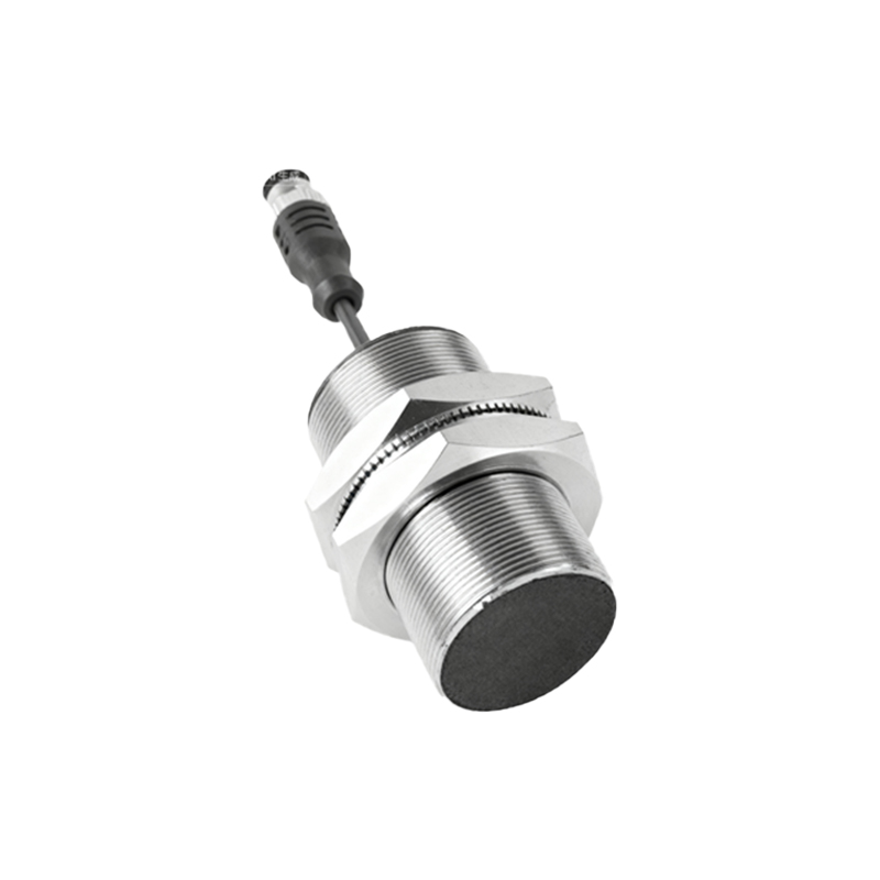
In industrial automation and control systems, three-wire proximity sensors are widely used for detecting the presence or absence of objects without physical contact. These sensors, which typically include a power supply wire (brown), a ground wire (blue), and a signal output wire (black), offer reliable performance in various applications. However, when multiple sensors need to be connected to a single controller input or when simplifying wiring is desired, wiring them in series becomes a practical solution. This article provides a detailed, step-by-step guide on how to correctly wire three-wire proximity sensors in series, ensuring safe and efficient operation.
First, it is essential to understand the basic wiring configuration of a standard three-wire DC proximity sensor. The brown wire is connected to the positive DC supply voltage (commonly 12-24V DC), the blue wire to the negative or ground, and the black wire serves as the output signal. In a typical setup, the output is either normally open (NO) or normally closed (NC), depending on the sensor type and application requirements. When an object is detected, the output switches state, sending a signal to the controller. For series wiring, the goal is to connect multiple sensors so that they collectively control a single circuit, often to trigger an action only when all sensors are activated or deactivated simultaneously.
To wire three-wire proximity sensors in series, follow these steps carefully. Begin by ensuring all sensors are of the same type (e.g., all NPN or all PNP) and compatible with the power supply voltage. Mixing sensor types can lead to circuit malfunctions or damage. For this example, assume we are using NPN sensors with normally open outputs, which are common in many industrial settings. Start by connecting the power supply: link the positive terminal of the DC power source to the brown wire of the first sensor. Then, connect the blue wire of the first sensor to the negative terminal of the power supply to complete its ground connection. This provides power to the first sensor independently.
Next, for the signal output wiring in series, connect the black output wire of the first sensor to the brown power wire of the second sensor. This configuration uses the output of the first sensor to supply power to the second sensor, creating a daisy-chain effect. Repeat this process for additional sensors: connect the black output wire of the second sensor to the brown wire of the third sensor, and so on. Finally, connect the black output wire of the last sensor in the series to the controller input or load device. It is crucial to verify that the total current draw of all sensors does not exceed the power supply or controller ratings, as series wiring can increase current flow in the circuit.
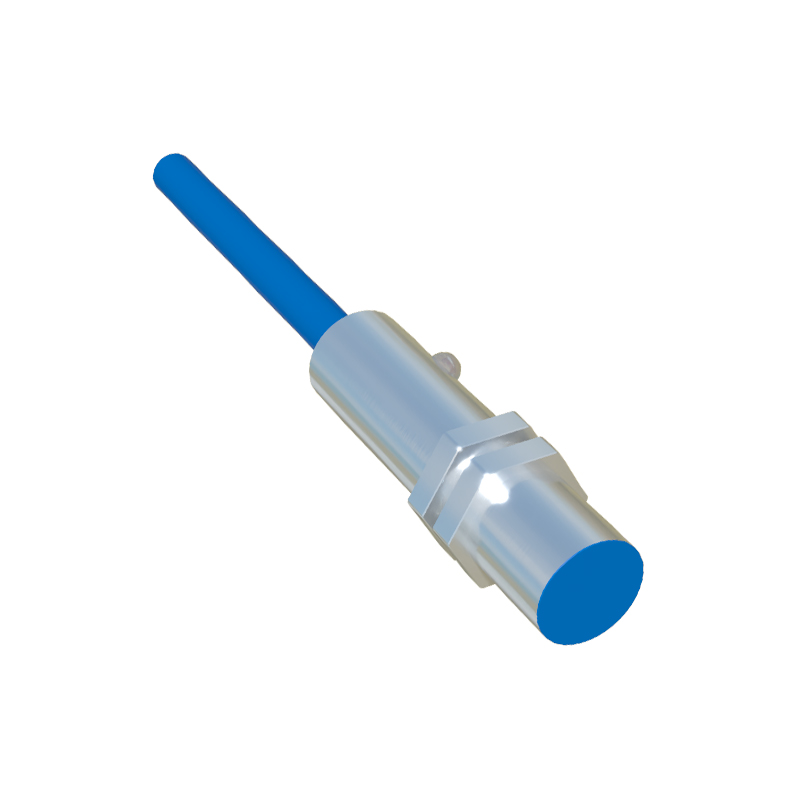
A key consideration in series wiring is the behavior of the output circuit. With normally open NPN sensors wired in series, the controller will only receive a signal (i.e., the circuit closes) when all sensors detect an object simultaneously. If any sensor fails to detect an object, the circuit remains open, and no signal is sent. This is useful for safety interlocks or multi-point verification systems. However, note that series wiring can introduce voltage drops across each sensor, potentially affecting performance. To mitigate this, use sensors with low voltage drop characteristics and ensure the power supply voltage is sufficiently high to compensate for cumulative drops. Additionally, always refer to the manufacturer’s datasheet for specific wiring diagrams and limitations.
In practice, testing the series-wired sensors is vital. After wiring, power on the system and check each sensor individually by placing an object within its detection range. Use a multimeter to measure voltage at key points, ensuring that each sensor outputs correctly and that the final signal reaches the controller as expected. Common issues in series wiring include incorrect polarity, mismatched sensor types, or loose connections, which can be troubleshooted by systematic inspection. For enhanced reliability, consider using shielded cables to reduce electrical noise, especially in environments with high interference.
In conclusion, wiring three-wire proximity sensors in series is an effective method for consolidating multiple sensor inputs into a single control signal. By following proper steps—matching sensor types, connecting outputs to subsequent power inputs, and accounting for voltage drops—engineers can achieve robust and efficient automation setups. This approach not only simplifies wiring but also enhances system logic for applications requiring coordinated sensor activation. Always prioritize safety by disconnecting power during installation and adhering to industry standards.