Proximity sensors are ubiquitous in industrial automation, robotics, and safety systems. Their ability to detect the presence or absence of an object without physical contact makes them indispensable. While complex, application-specific integrated circuits (ASICs) are common in commercial units, understanding a fundamental proximity sensor schematic is crucial for engineers for troubleshooting, customization, and foundational knowledge. This article breaks down a simple, effective inductive proximity sensor schematic, explaining its core components and operational principles.
The heart of most simple inductive proximity sensors is an LC oscillator circuit. "LC" stands for Inductor (L) and Capacitor (C). This circuit, when powered, generates a high-frequency oscillating magnetic field from the inductor coil, which serves as the sensor's active face. In a typical schematic, you will find a transistor (often a bipolar junction transistor or a MOSFET) configured as an oscillator. The inductor (the sensing coil) and a capacitor form the tank circuit that determines the oscillation frequency, usually in the range of 100 kHz to 1 MHz. Resistors set the bias point for the transistor, ensuring it operates in its active region to sustain oscillations.
When the oscillator is running with no target present, it produces a constant high-frequency signal. This signal is then fed into a demodulator and amplifier stage. A simple diode detector (a diode and a capacitor) can rectify the AC oscillation into a DC voltage. This DC voltage is then smoothed and compared against a reference voltage using a comparator circuit (e.g., an op-amp or a dedicated comparator IC). The output of this comparator is in a "high" or "on" state, indicating no target detected.
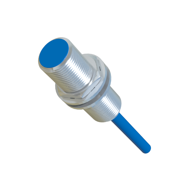
The core detection principle lies in the effect of a metallic target on the inductor. When a conductive metal object enters the oscillating magnetic field, eddy currents are induced on the surface of that object. These eddy currents draw energy from the oscillator circuit due to Lenz's Law, effectively increasing the "load" on the coil. This energy loss causes a decrease in the amplitude of the oscillation. The closer or larger the metal target, the greater the amplitude attenuation.
This change in amplitude is key. The demodulator stage now outputs a lower DC voltage. When this voltage falls below the comparator's set threshold (the trip point), the comparator's output switches state—from high to low. This low signal can then be used to drive an output stage. The output stage often consists of another transistor (like an NPN or a PNP) acting as a switch. When the comparator goes low, this output transistor turns on, allowing current to flow from the supply voltage through the load (e.g., a relay coil, PLC input, or an LED indicator). This provides a clear, switched signal: target present = output active.
A critical part of any practical sensor schematic is protection and stability. You will commonly see components like a Zener diode for voltage regulation or transient suppression, resistors for current limiting on the output transistor, and a power supply bypass capacitor to filter noise. For a two-wire DC sensor (which operates in series with the load), the schematic integrates a constant current sink circuit to maintain a minimum holding current while allowing the output switching device to shunt current when active.
Analyzing such a schematic provides deep insight. The sensitivity is influenced by the oscillator's design, the coil's geometry (size, number of turns), and the comparator's hysteresis (to prevent chatter). The sensing range is fundamentally limited by the strength and shape of the magnetic field. Non-ferrous metals like aluminum or copper affect the oscillator differently than ferrous metals like iron; they typically cause a frequency shift in addition to amplitude damping, which is why some simple circuits are tuned for a specific metal type.
In conclusion, a basic inductive proximity sensor schematic revolves around an LC oscillator, a detection/demodulation circuit, a comparator, and an output switch. Despite the simplicity, it elegantly demonstrates electromagnetic principles applied to solve a real-world detection problem. For engineers, being able to interpret this schematic aids in diagnosing failures—such as a damaged coil killing oscillations or a faulty output transistor—and in making informed decisions when selecting or integrating sensors into a larger system. While modern digital sensors incorporate microcontrollers for advanced features like programmability and diagnostics, the underlying physical detection mechanism and core circuit blocks remain remarkably consistent with this foundational design.