Proximity sensors are widely used in industrial automation for detecting the presence or absence of objects without physical contact. Their wiring and circuit design are critical for ensuring reliable operation in various applications, such as conveyor systems, robotic arms, and safety interlocks. This article delves into the practical aspects of proximity sensor wiring, covering common types, circuit configurations, and implementation guidelines.
There are several types of proximity sensors, including inductive, capacitive, and photoelectric sensors. Inductive sensors are ideal for detecting metallic objects, while capacitive sensors can sense both metallic and non-metallic materials. Photoelectric sensors use light beams to detect objects at a distance. Each type has specific wiring requirements that must be adhered to for optimal performance.
When wiring a proximity sensor, the first step is to identify its configuration: NPN (sinking) or PNP (sourcing). NPN sensors switch the negative side of the load, whereas PNP sensors switch the positive side. In a typical three-wire DC sensor, the wires are color-coded: brown for positive, blue for negative, and black for the output signal. For AC sensors, the wiring usually involves two wires: one for live and one for neutral, with the output integrated into the circuit.
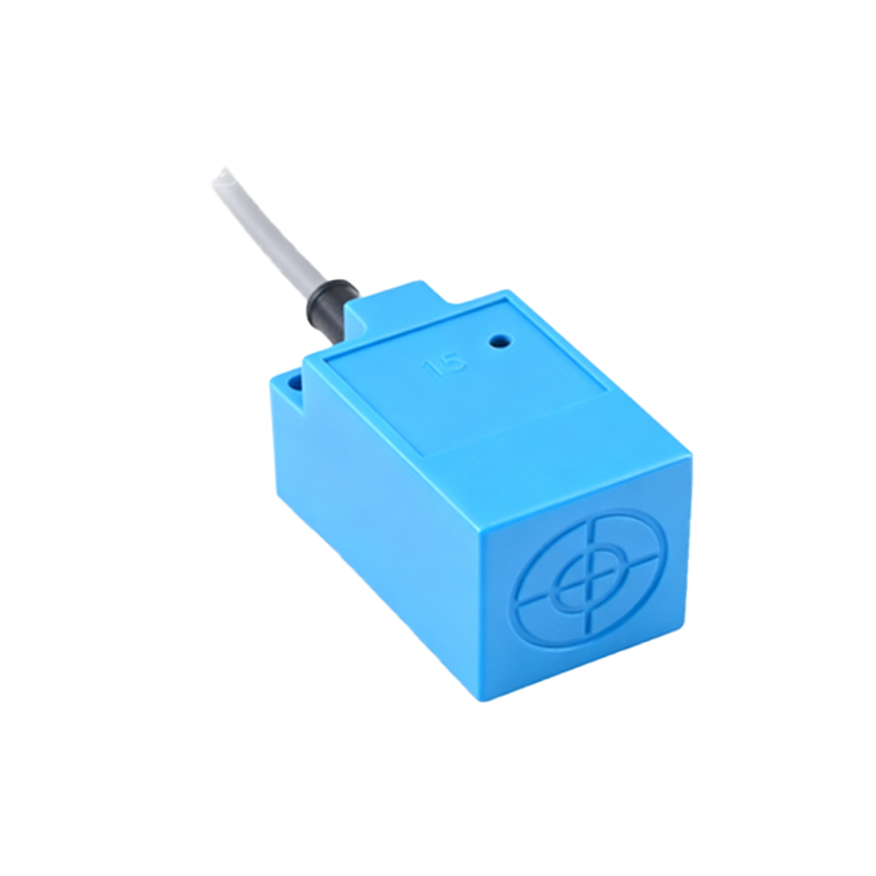
A practical circuit for an inductive proximity sensor involves connecting it to a programmable logic controller (PLC) or a relay. For a PNP sensor, the brown wire connects to the DC positive supply (e.g., +24V), the blue wire to the DC negative or ground, and the black wire to the input terminal of the PLC. A pull-down resistor may be added between the output and ground to ensure a clean signal. In NPN configurations, the black wire connects to the load, which is then linked to the positive supply, with the blue wire grounded.
Shielding and grounding are essential to prevent electrical noise interference, especially in environments with motors or high-frequency equipment. Use shielded cables and connect the shield to ground at one end only to avoid ground loops. Additionally, ensure the power supply matches the sensor's voltage rating (commonly 10-30V DC or 90-250V AC) to prevent damage.
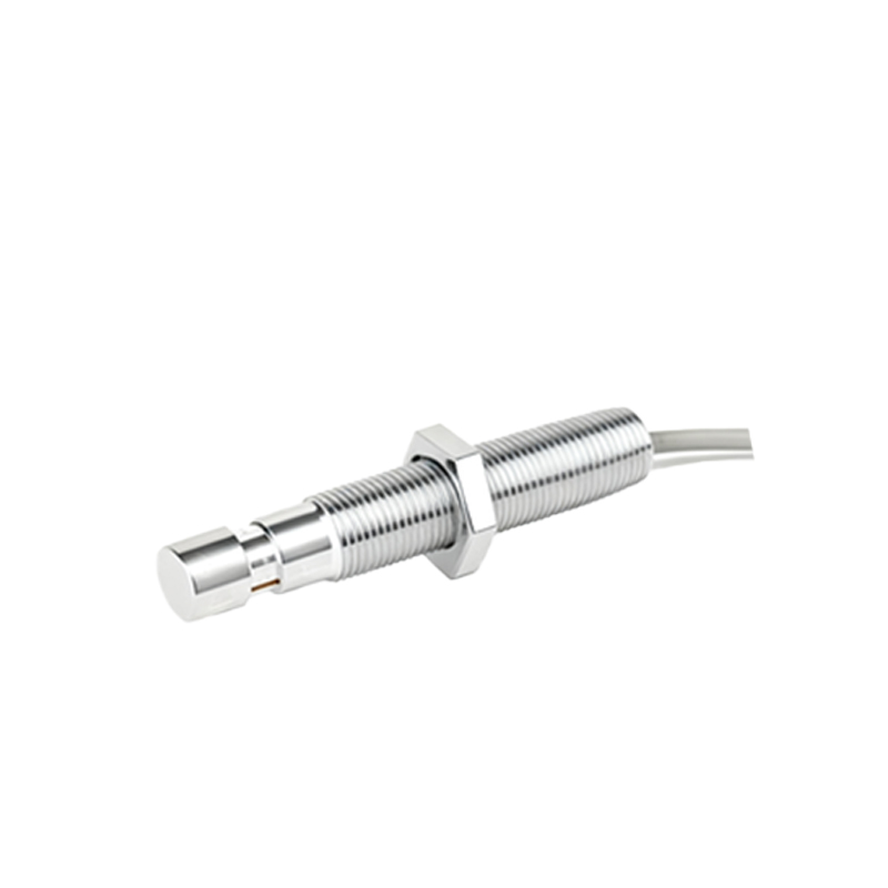
For integrating multiple sensors, consider using a modular wiring approach with terminal blocks or connectors to simplify maintenance. Label all wires clearly and follow industry standards, such as IEC 60947-5-2, for safety and compatibility. Testing the circuit with a multimeter or oscilloscope can help verify signal integrity and response time.
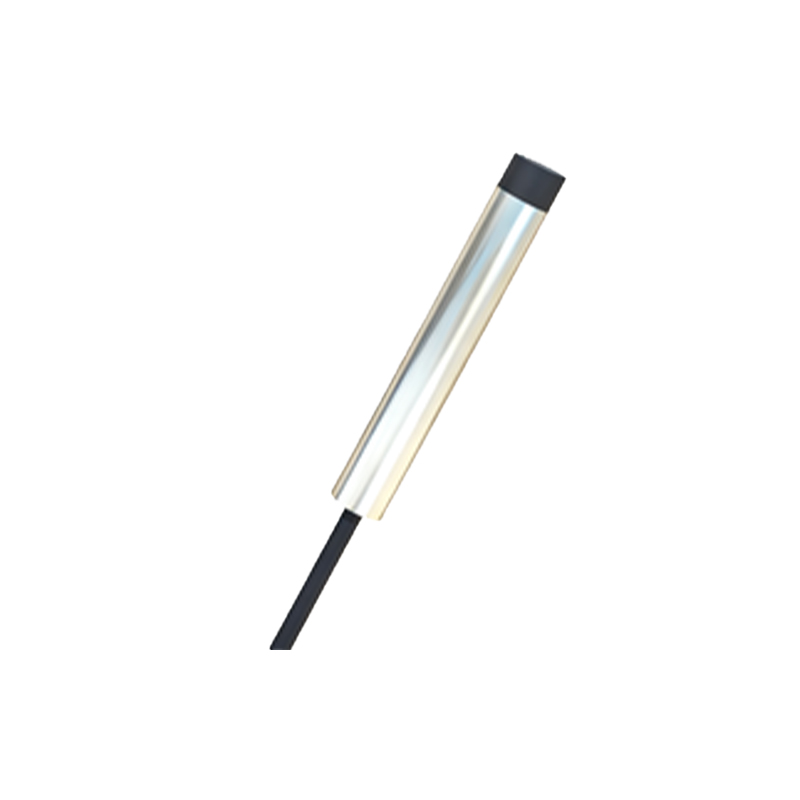
In summary, proper wiring of proximity sensors enhances system reliability and longevity. By understanding sensor types, configurations, and noise mitigation techniques, engineers can design robust circuits that meet industrial demands. Always refer to the manufacturer's datasheet for specific wiring diagrams and specifications to ensure correct implementation.