Inductive proximity sensors are fundamental components in modern industrial automation, offering non-contact detection of metallic objects. Their reliability, long service life, and resistance to harsh environments make them indispensable for tasks like position sensing, counting, and end-of-travel detection. Correct wiring is paramount to ensure optimal performance, safety, and system integrity. This guide details the standard wiring configurations and critical considerations for engineers and technicians.
An inductive proximity sensor operates on the principle of electromagnetic induction. It contains an oscillator circuit that generates a high-frequency electromagnetic field at its active face. When a metallic target enters this field, eddy currents are induced within the target, causing a change in the oscillator's amplitude. This change is detected by a threshold circuit, which subsequently switches the sensor's output state. The sensor itself typically consists of three main terminals, often designated as Brown (or +V), Blue (or 0V/Common), and Black (or Output). A fourth wire, usually White, may be present in certain configurations for complementary output or special functions.
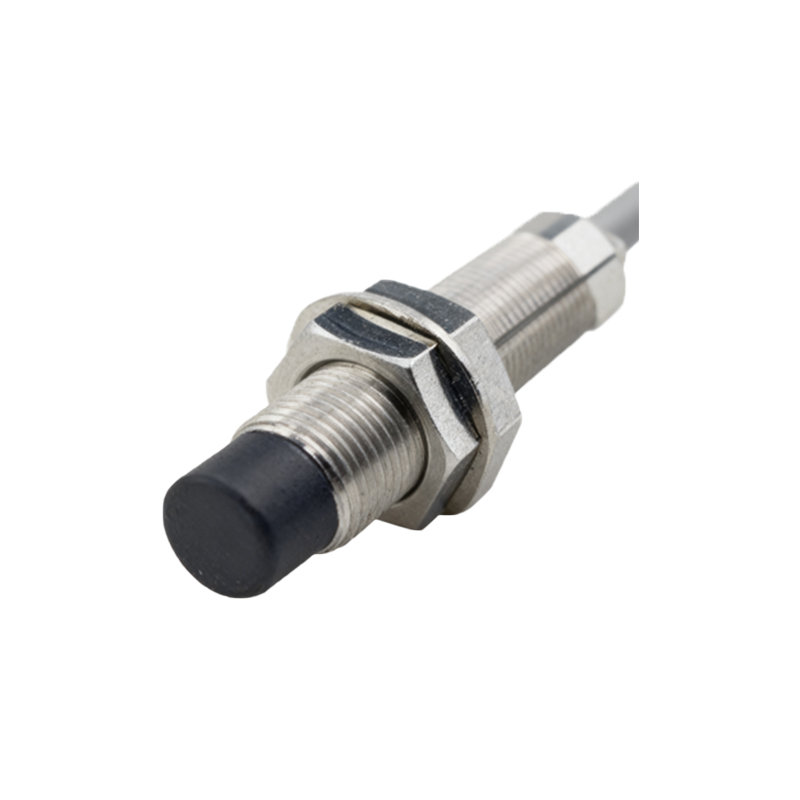
The two primary wiring schemes are based on the type of output transistor: PNP (sourcing) and NPN (sinking). Understanding the difference is crucial for compatibility with the controller, typically a Programmable Logic Controller (PLC).
PNP (Sourcing) Configuration: In a PNP sensor, the output transistor connects the load to the positive supply voltage when activated. The standard wiring is as follows:
Brown Wire: Connect to the positive terminal of the DC power supply (e.g., +24V DC).
Blue Wire: Connect to the negative terminal (0V) of the DC power supply and the common terminal of the load (e.g., PLC input module common).
Black Wire (Output): Connect to the signal input of the load (e.g., the specific PLC input point). When a target is detected, the PNP transistor switches ON, sourcing current from the +24V supply, through the sensor's output, to the PLC input, signaling a "TRUE" or "HIGH" state.
NPN (Sinking) Configuration: In an NPN sensor, the output transistor connects the load to ground (0V) when activated. The standard wiring is:
Brown Wire: Connect to the positive terminal of the DC power supply (+24V DC).
Blue Wire: Connect to the negative terminal (0V) of the DC power supply.
Black Wire (Output): Connect to the load. Here, the other side of the load must be connected to the positive supply. When a target is detected, the NPN transistor switches ON, sinking current from the load to the 0V, completing the circuit and signaling a "TRUE" or "LOW" state to the controller (assuming a sinking-input PLC module).
Selecting between PNP and NPN depends on the input circuit of the control system. Many European and global standards favor PNP wiring, while NPN is common in some Asian markets. Always consult the PLC and sensor datasheets.
For sensors with a complementary output (e.g., a NO and NC output), a four-wire configuration is used, often involving Brown (+V), Blue (0V), Black (NO output), and White (NC output). Wiring must be executed precisely as per the manufacturer's diagram.
Shielded Cables and Noise Immunity: In electrically noisy industrial environments, using shielded cables is highly recommended. The cable shield, typically a braided or foil layer, should be grounded at only one end—usually at the control panel—to prevent ground loops. This practice significantly reduces electromagnetic interference (EMI) that could cause false triggering.
Critical Installation and Safety Practices:
1. Power Supply: Always use a stable, regulated DC power supply, typically 10-30V DC, with correct polarity. Reverse polarity can permanently damage the sensor.
2. Load Current: Ensure the connected load (e.g., PLC input, relay coil) does not exceed the sensor's maximum switching current. A flyback diode is essential for inductive loads like relay coils to suppress voltage spikes.
3. Mounting: Maintain the specified sensing distance. Avoid mounting metallic sensors flush against a metal background; use non-ferrous brackets or provide the recommended lateral clearance to prevent shielding effects.
4. Wiring Integrity: Use crimped ferrules on stranded wires for secure termination. Ensure all connections are tight to prevent arcing and voltage drop. Route sensor cables away from high-voltage power lines and motor drives.
5. Testing: After wiring, verify operation with a target. Use a multimeter to check voltage at the output terminal in both sensing and non-sensing states.
Proper wiring of inductive proximity sensors is a straightforward yet critical task. Ad