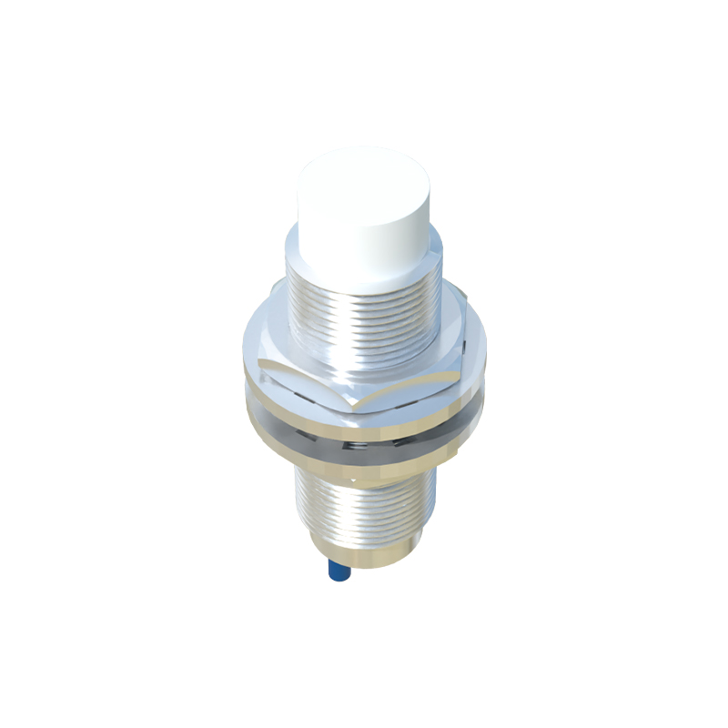
Proximity sensors are fascinating electronic components that detect the presence or absence of nearby objects without physical contact. They are widely used in applications ranging from smartphones and robotics to industrial automation and security systems. While commercial sensors are readily available, building your own can be a rewarding educational project that deepens your understanding of electronics and sensing technology. This guide will walk you through creating a basic infrared (IR) proximity sensor, a common and accessible type for DIY enthusiasts.
The core principle behind an IR proximity sensor involves emitting an infrared light beam and measuring the reflection. When an object comes close, infrared light bounces back to a receiver. The sensor then interprets this signal to determine proximity. For this project, you will need a few fundamental components: an IR LED (emitter), a photodiode or phototransistor (receiver), a suitable resistor (typically 220-330 ohms for the LED and 10k ohms for the receiver), an operational amplifier (like the LM358) for signal conditioning, a breadboard for prototyping, jumper wires, and a power source such as a 5V battery pack or USB power supply.
Begin by placing the components on your breadboard. Connect the anode (longer leg) of the IR LED to the positive power rail through a current-limiting resistor (220 ohms is a safe start). Connect its cathode to the ground rail. This setup ensures the LED emits infrared light consistently. Next, position the phototransistor. Its collector is usually connected to the positive rail through a pull-up resistor (10k ohms), and the emitter goes to ground. The voltage at the collector node will change based on the amount of IR light received. When no object is near, this voltage is high. When an object reflects IR light onto the phototransistor, its conductivity increases, pulling the collector voltage lower.
This voltage change is often too subtle for direct use. Therefore, we employ an operational amplifier (op-amp) configured as a comparator. Connect the non-inverting input (+) of the op-amp (like one channel of an LM358) to the junction between the phototransistor's collector and the pull-up resistor. Connect a potentiometer (e.g., 10k ohms) between the power rails and wire its wiper to the inverting input (-) of the op-amp. This potentiometer sets a reference voltage, acting as the sensitivity control. The output of the op-amp will swing high or low based on whether the sensor voltage is above or below this reference. You can connect the op-amp's output to an LED (with a series resistor) for visual feedback or to a microcontroller like an Arduino for further processing.
Once the circuit is assembled, power it on. You will need to calibrate it. Point the IR LED and phototransistor in the same general direction, ideally side-by-side. Adjust the potentiometer until the output LED just turns off when no object is present. Now, bring your hand or a white object close to the sensor. The reflected IR light should trigger the phototransistor, causing the op-amp's output to change state and light the indicator LED. The detection range is limited, typically a few centimeters, and is highly dependent on the object's reflectivity and ambient light conditions. For better performance, shield the sensor assembly from ambient light using a small tube or housing.
This basic sensor has limitations. Ambient sunlight or other IR sources can cause false triggers. More advanced designs incorporate modulation and demodulation techniques, where the IR LED is pulsed at a specific frequency, and the receiver circuit is tuned to that same frequency. This approach significantly improves noise immunity. For such a design, you would need additional components like a 555 timer to generate the pulse and a filter circuit. Alternatively, integrating a dedicated proximity sensor IC simplifies the design but reduces the hands-on learning aspect.
Building your own proximity sensor is an excellent entry point into the world of sensing and automation. It teaches fundamental concepts in optics, analog circuit design, and signal conditioning. The skills learned are transferable to other sensor types, such as ultrasonic or capacitive sensors. With a functional prototype, you can integrate it into small projects like an automatic tap, a robot obstacle detector, or a non-contact tachometer. Remember to experiment with component values and layouts to optimize performance for your specific application. The journey from a simple circuit on a breadboard to a reliable sensing tool encapsulates the practical spirit of electronics engineering.