In industrial automation systems, proximity sensors play a critical role in detecting the presence or absence of objects without physical contact. These sensors are widely used in applications such as material handling, assembly lines, and safety interlocks. While most proximity sensors are connected individually to a PLC (Programmable Logic Controller) or relay, there are scenarios where connecting two proximity sensors in series can offer significant advantages. This article explores the technical aspects, benefits, and practical considerations of wiring two proximity sensors in series, tailored for electrical engineers and automation professionals.
When two proximity sensors are connected in series, their output signals are linked in a single circuit path. Typically, this configuration uses normally open (NO) or normally closed (NC) contacts, depending on the desired logic. For example, in a safety-critical application, two inductive proximity sensors might be wired in series to ensure that both must detect an object (or the absence of one) before triggering an action, such as stopping a conveyor belt. This setup enhances reliability by reducing the risk of false triggers—if one sensor fails or is obstructed, the circuit remains open, preventing unintended operations.
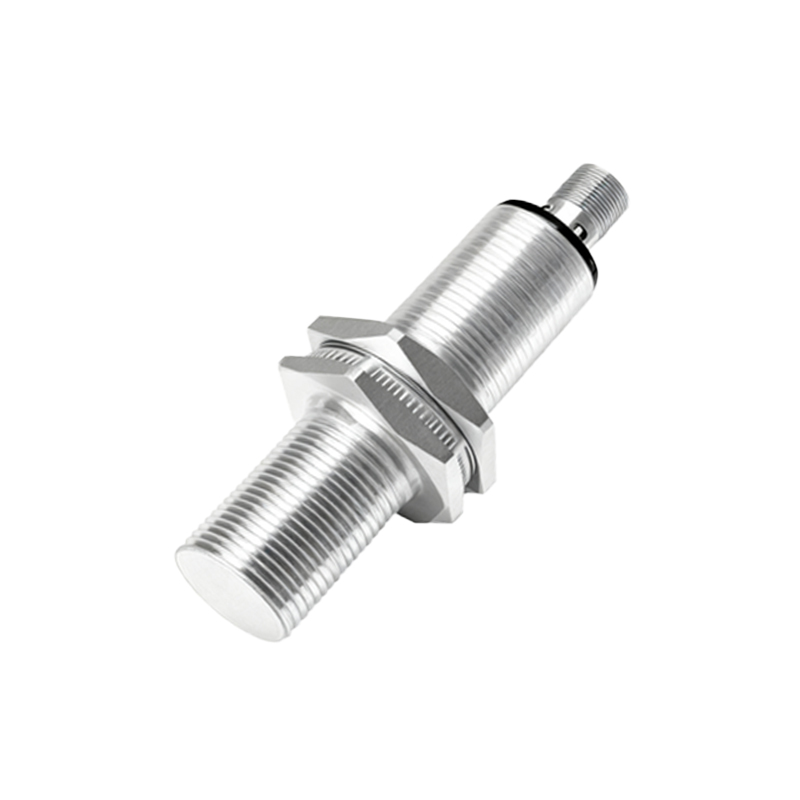
From an electrical perspective, connecting sensors in series requires careful attention to voltage, current, and load compatibility. Most industrial proximity sensors operate on DC (e.g., 10-30 V DC) or AC power supplies. When wired in series, the total voltage drop across the sensors must not exceed the supply voltage, and the current rating should support the combined load. Engineers must consult datasheets to verify parameters like leakage current and switching capacity. For instance, if each sensor has a maximum switching current of 200 mA, the series circuit should not exceed this limit to avoid damage or malfunction. Additionally, using shielded cables and proper grounding minimizes electromagnetic interference, which is crucial in noisy industrial environments.
One common application of series-connected proximity sensors is in machine guarding systems. By placing two sensors at different points along a hazardous area—such as near a robotic arm—the system ensures that both zones are clear before initiating movement. This redundancy improves safety compliance with standards like ISO 13849. Another use case is in packaging lines, where two sensors might monitor product alignment; only when both detect correct positioning does the sealing mechanism activate, reducing waste and improving efficiency.
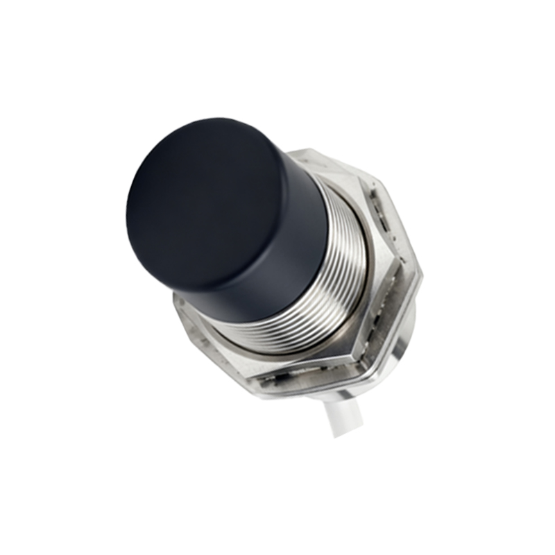
However, there are limitations to consider. Series connections can complicate diagnostics, as a fault in one sensor may affect the entire circuit. Using sensors with diagnostic outputs (e.g., LED indicators or IO-Link communication) can mitigate this issue. Moreover, not all proximity sensor types are suitable for series wiring—capacitive sensors, for example, may have higher leakage currents that interfere with signal integrity. It’s essential to test the configuration in a controlled setting before full deployment.
In summary, wiring two proximity sensors in series is a practical solution for enhancing safety, reliability, and precision in industrial automation. By understanding the electrical requirements and application-specific needs, engineers can design robust systems that leverage this simple yet effective technique. As Industry 4.0 evolves, integrating smart sensors with series connections may further optimize processes, making it a valuable skill for professionals in the field.