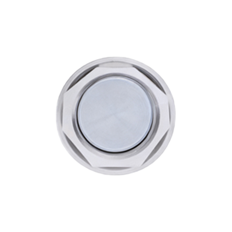
Magnetic proximity sensors are essential components in modern industrial automation, offering non-contact detection of ferromagnetic objects. Their robust construction and reliable performance make them suitable for harsh environments where traditional mechanical switches would fail. This article delves into the detailed structural composition of a typical inductive magnetic proximity sensor, explaining the function of each part and the underlying working principle.
The core structural elements of a standard tubular inductive magnetic proximity sensor can be categorized into several key sections. The foremost component is the sensing face or active surface, typically made from a durable, non-ferromagnetic material like stainless steel, PBT, or PTFE. This face protects the internal components and allows the magnetic field to penetrate. Directly behind this face lies the heart of the sensor: the ferrite core. This core is designed to concentrate and direct the oscillating magnetic field generated by the sensor outward from the sensing face.
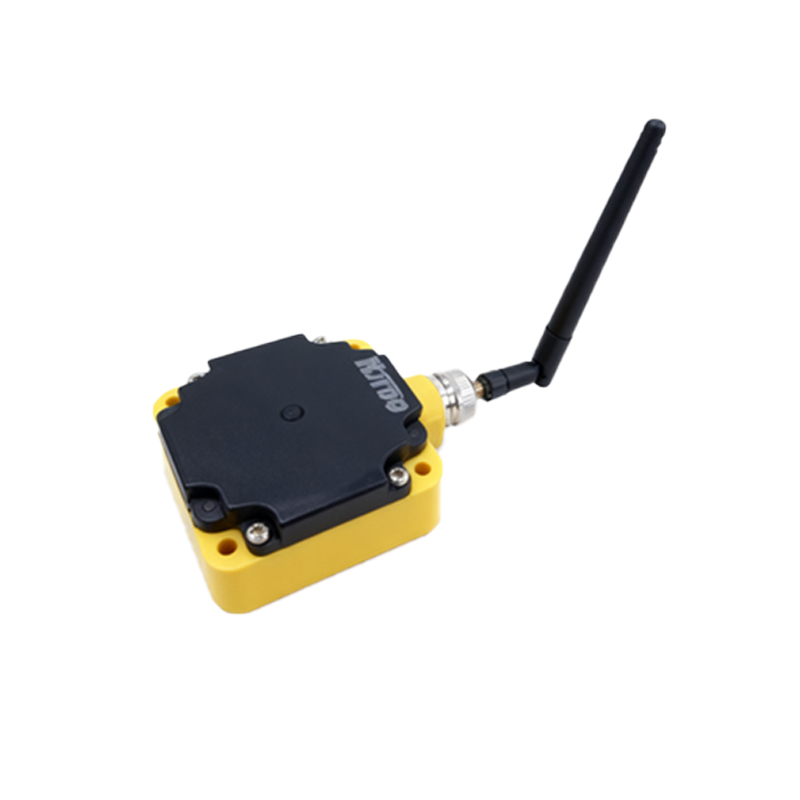
Wound around this ferrite core is a coil, which is part of an LC resonant circuit. This coil, along with a capacitor, forms the oscillator circuit. When powered, this circuit generates a high-frequency electromagnetic field that projects from the sensing face. The entire oscillator assembly is precisely positioned within a metal or high-strength polymer housing. This housing provides mechanical protection, environmental sealing (often rated IP67 or higher), and electromagnetic shielding to prevent interference from external fields.
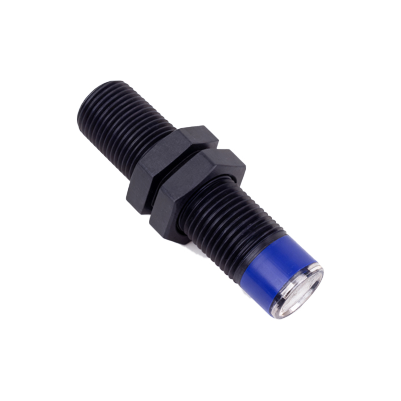
Integrated into the housing is the critical evaluation electronics module. This module typically contains the oscillator driver, an amplitude demodulator, a Schmitt trigger, and an output switching stage. The demodulator monitors the amplitude of the oscillations in the LC circuit. The housing also contains the connection area, which may include a pre-wired cable or a connector (e.g., M8, M12). For sensors with adjustable sensing ranges or other parameters, a potentiometer or programming interface may be included, though often sealed to prevent tampering.
The working principle is based on electromagnetic induction and eddy current losses. In its standby state (no target present), the internal LC oscillator runs at its resonant frequency, producing a constant amplitude high-frequency field. When a ferromagnetic target (like iron or steel) enters this active field, eddy currents are induced on the surface of the target. These eddy currents draw energy from the oscillator circuit, causing a measurable decrease in the oscillation amplitude. The demodulator circuit detects this amplitude drop. Once the amplitude falls below a predefined threshold set by the Schmitt trigger, the trigger circuit changes state, commanding the output switching stage (which could be a transistor for DC sensors or a triac for AC sensors) to activate. This changes the output signal from "off" to "on." When the target moves away, the oscillation amplitude recovers, and the output switches back to its original state.
This non-contact operation eliminates mechanical wear, ensuring a long operational life. The all-solid-state construction, with no moving parts, grants exceptional resistance to vibration, shock, and contamination from oil, dust, or coolants. The sensing distance, or switching distance, is a fixed characteristic determined by the coil design, core geometry, and oscillator frequency, and is standardized (e.g., Sn) according to international norms. Understanding this detailed structure is crucial for proper sensor selection, installation, and troubleshooting in applications ranging from machine tool position sensing and cylinder piston detection to conveyor line counting and speed monitoring.