Proximity sensors are critical components in modern industrial automation, enabling non-contact detection of objects with high precision and reliability. Proper calibration and debugging are essential to ensure these sensors perform accurately in diverse operating conditions. This guide outlines systematic steps for setting up, testing, and troubleshooting proximity sensors, tailored for engineers and technicians in the electrical and automation fields.
The first step in debugging a proximity sensor involves verifying the installation and electrical connections. Ensure the sensor is mounted securely at the correct distance and angle relative to the target object. Check the wiring according to the manufacturer’s datasheet, confirming power supply ratings (typically 10-30V DC for inductive sensors) and load connections. Incorrect wiring can lead to sensor failure or erratic behavior, so use a multimeter to test voltage levels at the sensor terminals. For inductive and capacitive sensors, ensure the sensing face is free from obstructions like dust, oil, or metal debris, which may interfere with detection.
Next, adjust the sensor’s sensitivity or sensing range to match the application requirements. Most proximity sensors feature a potentiometer or digital interface for calibration. Begin by placing a standard target object (e.g., a metal plate for inductive sensors) within the nominal sensing range. Gradually move the target closer to the sensor while monitoring the output signal via an LED indicator or oscilloscope. Fine-tune the sensitivity until the sensor triggers consistently at the desired distance. Avoid over-sensitivity, as it may cause false triggers from environmental noise or vibration. For capacitive sensors, adjust the threshold to ignore non-target materials like liquids or plastics.
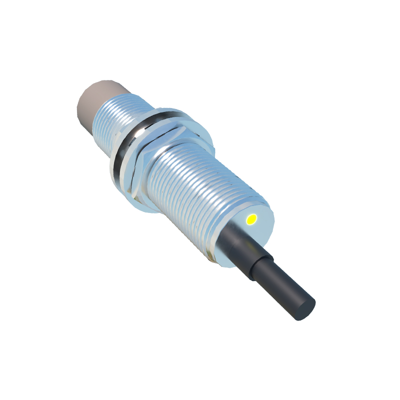
Environmental factors significantly impact sensor performance. Electrical noise from motors, relays, or frequency drives can disrupt sensor signals. To mitigate interference, use shielded cables and separate sensor wiring from high-voltage lines. In high-temperature or corrosive environments, select sensors with appropriate IP ratings and temperature tolerances. Additionally, consider target material properties: inductive sensors detect metals but may vary in response based on conductivity, while capacitive sensors react to both conductive and non-conductive materials. Test the sensor with actual production materials to validate detection consistency.
Debugging common issues requires methodical troubleshooting. If the sensor fails to detect objects, check for power supply faults, incorrect polarity, or damaged wiring. Use an oscilloscope to analyze the output waveform for anomalies like signal dropout or noise spikes. For intermittent operation, inspect for loose connections or environmental interference. In cases of false triggering, recalibrate the sensitivity or install a snubber circuit to suppress voltage transients. Log sensor behavior over time to identify patterns, such as failures during machine startup or specific operational cycles.
Advanced calibration techniques involve using programmable logic controllers (PLCs) or dedicated calibration tools. Integrate the sensor with a PLC to monitor real-time data and adjust parameters via software. For networked sensors, leverage industrial protocols like IO-Link to access diagnostic information, such as operating hours, temperature readings, and signal strength. This data facilitates predictive maintenance, reducing downtime. Always refer to the manufacturer’s manual for model-specific features, such as teach-in functions or hysteresis settings, which optimize performance for dynamic applications.
Finally, document the calibration process and results for future reference. Record settings like sensitivity levels, sensing distances, and environmental conditions. Regular maintenance, including cleaning sensor faces and retesting calibration, ensures long-term reliability. By following these steps, engineers can maximize sensor accuracy, enhance system efficiency, and minimize operational disruptions in industrial automation setups.