In the realm of industrial automation and machinery, proximity sensor modules are indispensable components for non-contact detection of objects. Their reliability hinges significantly on correct wiring, a fundamental yet critical task for any electrical engineer or technician. This guide provides a detailed, step-by-step overview of standard wiring methods for common proximity sensor modules, adhering to industry best practices and safety protocols.
First and foremost, safety is paramount. Always disconnect power from the control circuit before initiating any wiring procedure. Verify the voltage is zero using a multimeter. Ensure you have the correct sensor datasheet for the specific model (e.g., inductive, capacitive, or photoelectric) and its electrical specifications, including operating voltage (commonly 10-30V DC or 90-250V AC), current rating, and output type (PNP/NPN sourcing/sinking for DC, or NO/NC for AC/DC).
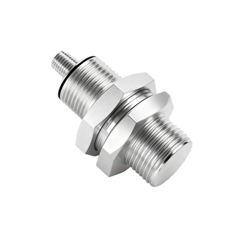
For a standard 3-wire DC proximity sensor (the most common type), the wires are typically color-coded: brown for positive (+V), blue for negative (0V or common), and black for the output signal. The wiring procedure is as follows:
1. Connect the blue wire to the DC power supply's negative terminal or the common ground point of the PLC/digital input module.
2. Connect the brown wire to the DC power supply's positive terminal (e.g., +24VDC).
3. Connect the black output wire. This step depends on the sensor's output configuration and the load (e.g., a PLC input).
For a PNP (sourcing) sensor: The black wire outputs a positive voltage when activated. Connect it to the positive side of your load (e.g., the PLC input point). The other side of the load must be connected to the power supply negative (blue wire/common).
For an NPN (sinking) sensor: The black wire acts as a path to negative when activated. Connect it to the negative side of your load. The positive side of the load must be connected to the power supply positive (brown wire).
It is crucial to match the sensor type (PNP/NPN) with the input circuit of your controller. Mismatching can lead to malfunction or damage. Always install a protective fuse (typically 1-3A) in the positive supply line close to the power source. For noise immunity in electrically noisy environments, use shielded cables, grounding the shield at only one end (usually the control panel end), and keep sensor cables away from power lines and motor drives.
For 2-wire AC/DC sensors, wiring is simpler but requires careful attention to load compatibility. These sensors have two wires, acting like a switch in series with the power line and the load. Connect one wire to the AC or DC power source (L1 or +), and connect the other wire to one terminal of the load. The load's other terminal connects back to the neutral (N) or negative (-) of the power supply. A critical consideration is the leakage current. Even when "off," a 2-wire sensor allows a small leakage current to pass. If the connected load (like a PLC input) has a very high impedance, this tiny current might be enough to keep it falsely activated. Using a bleeder resistor in parallel with the load is often necessary to bypass this leakage current.
For 4-wire sensors, which feature two separate outputs (e.g., one NO and one NC, or a complementary PNP/NPN pair), the principle remains the same. Identify the power wires (brown/blue) and connect them first. Then, connect the output wires (often black and white) to their respective loads according to the required logic, following the PNP/NPN rules.
After completing all connections, double-check every terminal for tightness and correct placement. Visually inspect for any pinched wires or loose strands. Only then, re-apply power. Test the sensor's functionality by introducing a target object within its sensing range. Use a multimeter to verify the output voltage changes correctly or observe the indicator LED on the sensor and the corresponding input indicator on your PLC.
Common pitfalls to avoid include: incorrect voltage application, mixing up PNP and NPN wiring schemes, neglecting leakage current in 2-wire systems, forgetting protective fusing, and poor cable management leading to noise or physical damage. Proper wiring not only ensures immediate functionality but also guarantees long-term stability, reduces downtime, and upholds the safety of the entire system. By methodically following the sensor's documentation and these fundamental electrical principles, engineers can ensure robust and reliable integration of proximity sensor modules into any automated application.