Proximity sensors, particularly the widely used 80 series inductive models, are fundamental components in modern industrial automation. Their ability to detect the presence or absence of metallic objects without physical contact ensures reliability, longevity, and precision in countless applications, from conveyor systems to robotic assembly lines. Proper setup is not merely a matter of functionality; it is critical for optimizing performance, ensuring safety, and maximizing the sensor's operational lifespan. This guide provides a detailed, step-by-step approach to correctly installing and configuring an 80 series proximity sensor, adhering to industry best practices.
Before initiating any setup procedure, the paramount first step is to consult the specific datasheet provided by the sensor manufacturer. While 80 series sensors share common principles, specifications for sensing distance, voltage range, output type (PNP/NPN, NO/NC), housing material, and electrical connections can vary. Always ensure the work area is de-energized following proper lockout-tagout (LOTO) protocols to prevent electrical shock or unintended machine activation.
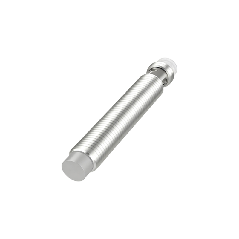
The physical installation begins with selecting an appropriate mounting location. The sensor must be securely fastened using the correct hardware, typically provided with the unit. For barrel-style sensors, ensure the mounting nut is tightened to the specified torque to prevent loosening from vibration while avoiding over-tightening, which can damage the housing. The sensing face must have a clear, unobstructed path to the target object. Maintain the specified nominal sensing distance (Sn), usually a percentage of the rated sensing distance. For instance, if an 80 sensor has an 8mm rated distance, a typical installation gap might be set at 75% of that, or 6mm, to account for mechanical tolerances and temperature drift. Crucially, ensure the target object is within the sensor's detectable range and made of the correct material (e.g., mild steel for standard inductive sensors). Non-ferrous metals like aluminum or copper have a reduced sensing factor, which must be accounted for in the gap calculation.
Wiring is the next critical phase. Identify the sensor's connection diagram, usually etched on the body or found in the manual. A standard 3-wire DC sensor will have leads for brown (positive/V+), blue (negative/0V), and black (output signal). For a 4-wire version, a second output (often white) may be present. Connect the brown wire to the positive DC supply terminal and the blue wire to the negative/common terminal, strictly observing the voltage range (commonly 10-30V DC). Incorrect polarity can permanently damage the device. The black output wire is connected to the load, such as a programmable logic controller (PLC) input, a relay coil, or an indicator lamp. It is essential to integrate a protective device like a fuse or circuit breaker into the supply line. For sensors in electrically noisy environments, using shielded cable with the drain wire properly grounded at the control panel end is highly recommended to prevent electromagnetic interference (EMI) from causing false triggers.
Once physically installed and wired, power on the system for adjustment and testing. Most 80 series proximity sensors feature a built-in indicator LED, typically red or yellow, which illuminates when the target is detected. This LED is an invaluable diagnostic tool. Manually introduce the target material to the sensing face. Observe the indicator light and verify the state change at the control system (e.g., the PLC input LED should turn on/off correspondingly). Fine-tune the mounting distance if the activation is inconsistent. If the sensor has a sensitivity adjustment potentiometer, use a non-metallic tool to make minor adjustments while testing with the target at the operational extremes. Avoid setting the sensitivity excessively high, as this can make the sensor prone to detecting background metal or noise.
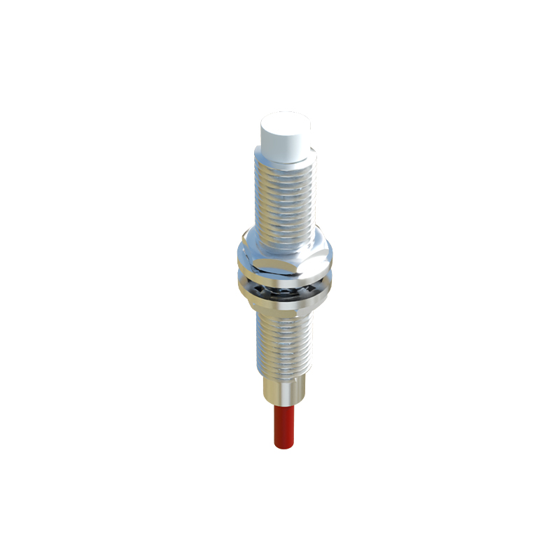
Finally, conduct a comprehensive operational test under real or simulated working conditions. Cycle the target object repeatedly at the intended speed and verify consistent detection over dozens of cycles. Check for any interference from adjacent metal structures, other sensors, or power cables. Monitor the sensor's performance over a period, noting any temperature-related drift if the environment is subject to significant thermal variation. Document the installation details, including part number, serial number, supply voltage, and gap setting, for future maintenance reference.
Routine maintenance, though minimal for these solid-state devices, involves periodic inspection for physical damage, accumulation of metallic debris on the sensing face (which can reduce effective range), and verification of secure electrical connections. By meticulously following these setup and verification steps, engineers and technicians can ensure their 80 proximity sensors deliver the robust, fail-safe performance required in demanding industrial automation environments, thereby reducing downtime and enhancing overall system productivity.