Proximity sensors are fundamental components in modern automation, consumer electronics, and industrial safety systems. They detect the presence or absence of an object within a specific range without physical contact. Ensuring these sensors function correctly is paramount, making systematic proximity sensor testing a critical process for engineers, technicians, and quality assurance teams. This guide outlines the core testing methodologies, equipment, and best practices to verify sensor performance and reliability.
The foundation of any test begins with understanding the sensor type. Inductive sensors detect metallic objects, capacitive sensors respond to both metallic and non-metallic materials, and photoelectric sensors use light beams. Ultrasonic sensors employ sound waves, while Hall Effect sensors react to magnetic fields. Each type requires a tailored testing approach. The primary parameters under evaluation are sensing distance, repeatability, hysteresis, and response time.
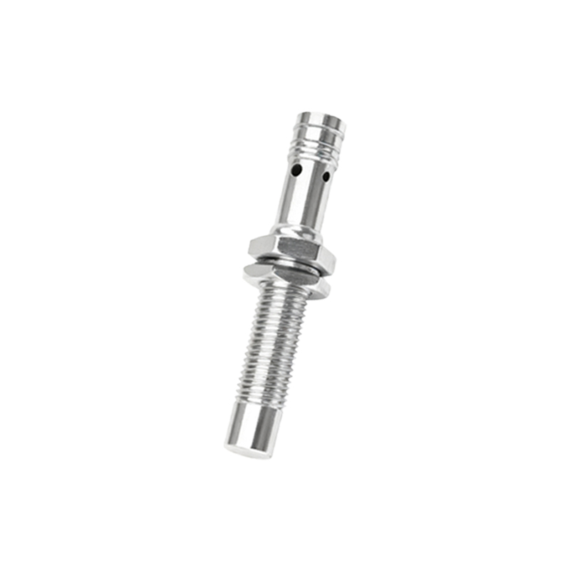
Sensing distance, often called the nominal sensing distance (Sn), is the first critical test. The standard method involves using a precisely defined standard target. For an inductive sensor, this is typically a square of mild steel with a thickness equal to the sensor's face diameter. The target is mounted on a calibrated linear positioning system or a high-precision gauge. The sensor is powered according to its specifications, and the target is moved slowly towards the sensing face. The point at which the sensor's output switches state is recorded as the actual sensing distance. This is compared to the manufacturer's stated Sn, with acceptable tolerances usually defined in datasheets, often within ±10%. Testing should be conducted under controlled environmental conditions, as temperature can affect performance.
Repeatability testing assesses the sensor's consistency. Using the same setup, the target is brought to the switch point multiple times (e.g., 100 or 1000 cycles) from the same direction. The variation in the measured switch point is the repeatability error, a crucial metric for high-precision applications. High-quality sensors exhibit minimal deviation.
Hysteresis is the difference between the switch-on point (as the target approaches) and the switch-off point (as the target recedes). This built-in characteristic prevents output oscillation when a target is positioned exactly at the sensing limit. To test it, the target is moved past the sensor until it activates, then slowly withdrawn until it deactivates. The distance between these two points is the hysteresis, usually expressed as a percentage of the sensing distance. Verifying this value ensures stable switching behavior.
Response time testing evaluates how quickly the sensor can react to a changing target. This is vital for high-speed automation. A high-speed actuator or a rotating disk with targets is used to move an object in and out of the sensing field at a known frequency. An oscilloscope is connected to the sensor's output signal to measure the delay between the target's edge crossing the sensing point and the output state change. This test confirms the sensor can keep up with the required operational speed.
Environmental and robustness tests are equally important. Temperature cycling tests validate operation across the sensor's specified range. Ingress Protection (IP) rating tests, such as exposure to dust and water sprays, confirm housing integrity. For applications with electrical noise, such as near motors or welders, testing for electromagnetic compatibility (EMC) is essential to ensure the output is not influenced by interference. Vibration and shock tests may also be necessary for harsh industrial environments.
For photoelectric and ultrasonic sensors, additional factors like target color, reflectivity, material, and ambient light (for photoelectric) must be considered. Testing should involve a representative sample of the actual targets the sensor will encounter. Ultrasonic sensor testing must account for factors like air temperature and humidity, which affect sound wave propagation.
A practical testing setup often includes a programmable logic controller (PLC) or a data acquisition (DAQ) system to log results, a stable power supply, calibrated measurement tools, and fixtures to hold the sensor and target securely. Creating a detailed test protocol that defines the procedures, pass/fail criteria, and equipment used is a best practice that ensures consistency and traceability.
Regular calibration of test equipment is non-negotiable for maintaining accuracy. Furthermore, testing a statistical sample from a production batch, rather than just a single unit, provides confidence in overall product quality. For end-users, implementing a periodic functional check as part of preventive maintenance can catch sensor drift or failure before it causes downtime.
In conclusion, thorough proximity sensor testing is not a single activity but a multi-faceted process. By methodically evaluating key operational parameters under controlled and real-world conditions, one can guarantee that these silent sentinels perform their detection duties reliably, safeguarding both processes and productivity. A robust testing regimen ultimately reduces machine downtime, improves product quality, and enhances system safety.