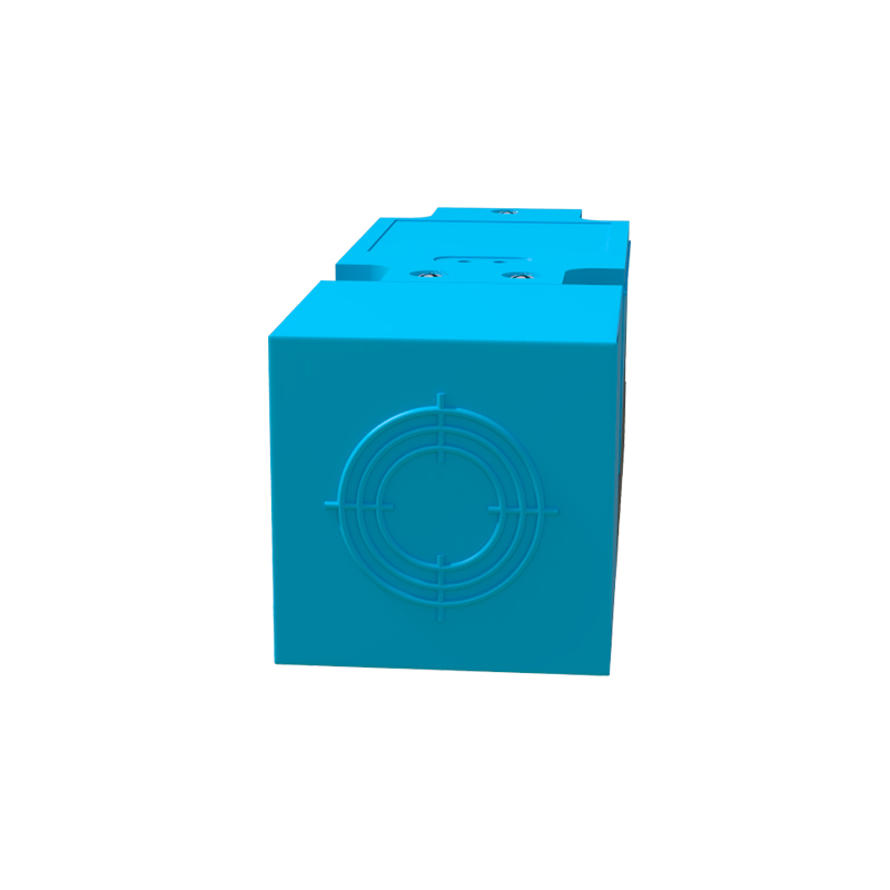
Proper terminal connection is a fundamental aspect of ensuring the reliable and safe operation of proximity switch sensors in industrial automation. These non-contact sensors, which detect the presence or absence of objects, depend on correct electrical interfacing to communicate effectively with control systems like PLCs. Understanding the terminal types, wiring standards, and common pitfalls is essential for technicians, engineers, and maintenance personnel.
A proximity sensor terminal block typically houses several connection points. The most common configuration includes three wires: brown, blue, and black. The brown wire is universally designated for the positive DC supply voltage (often 10-30V DC). The blue wire is the common negative or 0V DC return line. The black wire is the output signal line. For sensors with a Normally Open (NO) output, the black wire switches to supply voltage when a target is detected. For Normally Closed (NC) types, it switches off. Some sensors feature additional wires for a second complementary output, diagnostic functions, or analog current output. It is critical to consult the sensor's datasheet or nameplate before wiring, as colors and functions can vary by manufacturer and model (e.g., NPN vs. PNP sourcing).
The choice between NPN (sinking) and PNP (sourcing) output types dictates the wiring scheme to the PLC input module. An NPN sensor switches the negative (0V) line to the load. In a typical setup, the load (like a PLC digital input) is connected between the sensor's black wire (output) and the positive supply. The PLC input common is tied to positive. Conversely, a PNP sensor switches the positive voltage line. Here, the load is connected between the sensor output and the negative supply, with the PLC input common connected to 0V. Mismatching these with the PLC input type is a primary cause of sensor malfunction.
For reliable connections, use ferrules or properly tinned wire ends on stranded conductors when inserting them into screw terminals. This prevents stray strands from causing short circuits. Ensure the terminal screws are tightened to the manufacturer's specified torque to avoid loose connections, which lead to intermittent operation, voltage drops, and heat generation. For sensors in high-vibration environments, consider using sensors with spring-cage terminals or supplemental strain relief. Always follow lock-out/tag-out procedures and verify power is off before making connections.
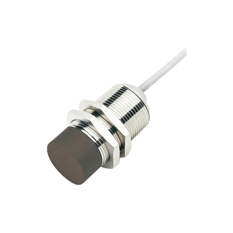
Shielding is vital for sensors with analog outputs or those operating in electrically noisy environments. The shield drain wire from the cable should be connected to the functional earth (FE) terminal, if present, at the sensor housing. This terminal is distinct from the protective earth (PE). The shield should be grounded at one end only, typically at the control panel, to prevent ground loops. Maintaining proper separation between high-voltage power lines and sensor cables minimizes inductive coupling and electromagnetic interference.
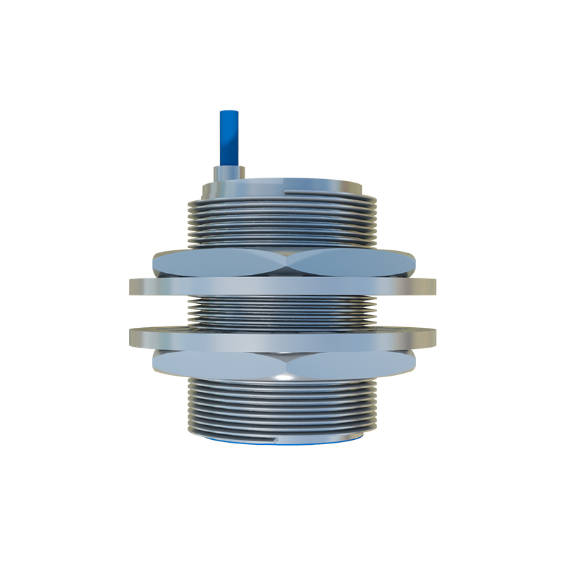
Common installation errors include incorrect voltage application, which can instantly damage the sensor's internal electronics. Verify the supply voltage matches the sensor rating. Overlooking the load current limit is another mistake; the sensor's solid-state output can be damaged if the connected load draws excessive current. Always check the maximum load specification. Finally, ensure the sensor body is properly mounted and the sensing face is clear of obstructions, as metallic mounting brackets or debris in the sensing field can cause erratic behavior.
In summary, meticulous attention to terminal connection details—from identifying wire functions and matching output types to employing secure wiring practices and noise mitigation—forms the backbone of a robust sensing system. Adhering to these principles maximizes sensor longevity, minimizes downtime, and ensures accurate signal transmission for automated processes.