In industrial automation and control systems, proximity switches are indispensable components for detecting the presence or absence of objects without physical contact. Among them, 12V DC proximity sensors are widely favored for their compatibility with low-voltage circuits, safety, and ease of integration. This article provides a comprehensive guide to the wiring diagram and installation practices for 12V proximity switch sensors, ensuring optimal performance and reliability in various applications.
A 12V proximity switch sensor typically consists of three key terminals: positive (V+), negative (V-), and output (OUT). The wiring diagram follows a standard configuration:
1. Power Supply Connection: Connect the positive terminal (V+) of the sensor to the 12V DC power source's positive wire. The negative terminal (V-) should be linked to the power source's negative wire, completing the circuit. It is crucial to verify the voltage rating to prevent damage—using a power supply exceeding 12V can lead to sensor failure.
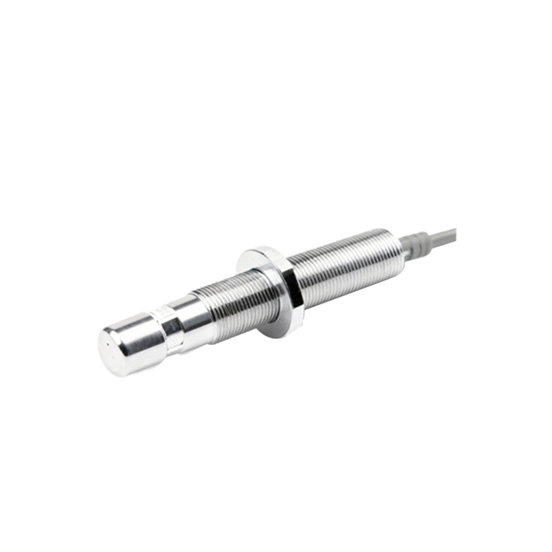
2. Output Signal Connection: The output terminal (OUT) transmits the detection signal to a controller, such as a PLC (Programmable Logic Controller) or relay. For normally open (NO) sensors, the output closes when an object is detected, allowing current to flow. In normally closed (NC) types, the output opens upon detection. Ensure the load (e.g., PLC input module) matches the sensor's output type (e.g., NPN or PNP) and current capacity.
3. Shielding and Grounding: To minimize electrical noise interference in industrial environments, use shielded cables for wiring and ground the shield at one end (preferably the controller side). Avoid running sensor wires parallel to high-voltage lines to reduce cross-talk.
Installation best practices include:
- Mounting Position: Install the sensor perpendicular to the target object's approach direction for accurate detection. Maintain the specified sensing distance—typically 2-10 mm for inductive sensors—and avoid metal obstacles that could cause false triggers.
- Environmental Considerations: 12V proximity sensors are suitable for dry, indoor settings. For harsh conditions (e.g., moisture, dust), opt for IP67-rated models. Temperature ranges should stay within -25°C to 70°C to ensure longevity.
- Testing and Calibration: After wiring, power the system and test with a target object. Use a multimeter to check output voltage signals: 0V indicates no detection, while ~12V confirms activation. Adjust mounting as needed for consistent response.
Common issues and solutions:
- No Output Signal: Verify power connections and voltage levels. Inspect for loose wires or incorrect polarity.
- Intermittent Operation: Check for environmental interference or insufficient sensing range. Ensure the target material is compatible (e.g., inductive sensors detect metals only).
- Overheating: Confirm the load current does not exceed the sensor's rating (usually below 200mA). Add a protective resistor if necessary.
In summary, proper wiring and installation of 12V proximity switch sensors enhance system efficiency and reduce downtime. Always refer to the manufacturer's datasheet for specific details, as designs may vary by model. By following this guide, engineers can achieve reliable object detection in automation setups, from conveyor belts to robotic arms.