In industrial automation and machinery, proximity sensors serve as the silent sentinels of operational integrity. These non-contact devices detect the presence or absence of objects, playing a critical role in positioning, counting, and safety interlock systems. When a proximity sensor fault light illuminates on a control panel or HMI, it signals a disruption in this vital function. For electrical engineers and maintenance technicians, a systematic approach to diagnosing and resolving this fault is paramount to minimizing downtime and ensuring process continuity.
The activation of a proximity sensor fault indicator is a symptom, not the root cause. The underlying issue can stem from the sensor itself, its wiring, the target object, or the connected control system. A logical, step-by-step diagnostic procedure is essential.
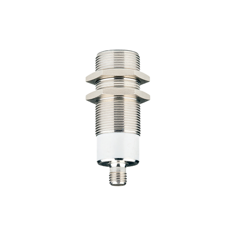
Initial Visual and Operational Checks
Begin with a basic but crucial inspection. Verify the state of the indicator lights on the sensor housing itself. Most industrial proximity sensors feature an LED that confirms power and output status. A complete absence of light suggests a power supply issue. If the sensor's LED is on but the machine's fault light persists, the problem may lie downstream. Next, inspect the sensor for obvious physical damage—cracks in the housing, bent or broken sensing faces, or signs of impact. Examine the installation: ensure the sensor is securely mounted and properly aligned with its target. Even a slight misalignment can cause intermittent detection failures, especially in inductive or capacitive sensors. Check the target object for changes in material, size, or surface condition (e.g., excessive dirt, paint buildup, or corrosion) that could affect the sensor's effective sensing range.

Electrical and Signal Verification
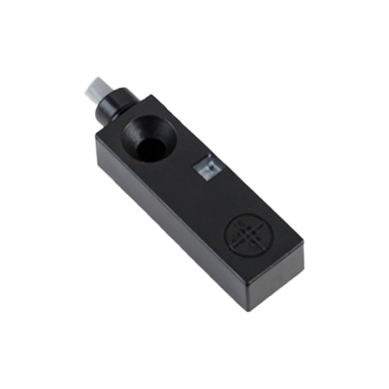
If visual checks yield no results, proceed with electrical diagnostics using a multimeter. First, confirm the supply voltage at the sensor's terminals. Compare the measured value against the sensor's specified operating range (commonly 10-30V DC for PNP/NPN types). Voltage outside this range, often due to a failing power supply or excessive voltage drop in long cable runs, will cause malfunction.
Next, test the sensor's output signal. For a DC 3-wire sensor, disconnect the output wire from the PLC input module. With the target present in the sensing field, measure the voltage between the output wire and the common (0V). A PNP (sourcing) sensor should output a voltage close to the supply voltage; an NPN (sinking) sensor should pull the voltage close to 0V when active. The absence of a correct signal shift indicates internal sensor failure. Also, perform a continuity and insulation resistance test on the cabling. Look for short circuits, open circuits, or insulation breakdown caused by pinching, abrasion, or chemical exposure. Don't forget to check the integrity of the cable glands and connections at both the sensor and control cabinet ends—loose terminals are a frequent culprit.
Environmental and Interference Factors
Proximity sensors operate in harsh industrial environments. Consider external factors that could impede performance. Accumulation of metallic swarf on an inductive sensor face can cause it to latch on. Excessive dust, oil, or coolant on a capacitive sensor can alter its dielectric constant and sensing characteristics. Strong electromagnetic interference (EMI) from nearby variable frequency drives (VFDs), welding equipment, or high-current cables can induce noise into sensor signals, leading to erratic behavior. Ensure sensor cables are properly shielded, grounded at one end only as per manufacturer guidelines, and routed away from power lines. For sensors in high-vibration areas, internal component fatigue or connection loosening can occur over time.
Advanced Diagnostics and Replacement
If basic checks are inconclusive, consult the sensor's datasheet for specific performance parameters like nominal sensing distance (Sn), hysteresis, and switching frequency. Using a feeler gauge or calibrated target, you can test if the actual sensing distance has degraded significantly from its nominal value, indicating aging or internal component drift. Sometimes, the issue is not the sensor but the load. Check the connected input module on the PLC. A faulty input channel or an incorrectly configured sinking/sourcing input relative to the sensor type can manifest as a sensor fault. Use the PLC's diagnostic software to monitor the real-time status of the input address.
When replacement is necessary, ensure the new sensor matches all key specifications: sensing principle (inductive, capacitive, ultrasonic), sensing distance, output type (PNP/NPN, NO/NC), housing material (e.g., stainless steel for washdown areas), and electrical ratings. After installation, recalibrate or adjust the positioning if needed, and document the change in maintenance logs.
A lit proximity sensor fault light is a call to action that demands a disciplined diagnostic routine. By methodically eliminating potential causes—from power and wiring to the sensor and its environment—engineers can swiftly restore functionality. This proactive troubleshooting not only fixes the immediate issue but also contributes to