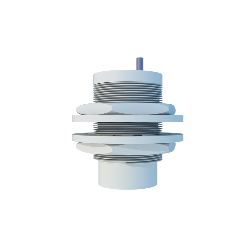
Injection molding stands as a cornerstone manufacturing process for proximity switch sensor housings and components, directly influencing device reliability, performance consistency, and cost-effectiveness. This guide details the critical methodologies and material considerations specific to producing high-quality sensor enclosures. The process begins with meticulous mold design, which must account for the sensor's functional geometry, including precise cavities for the sensing face, wiring conduits, and mounting threads or brackets. Venting channels are crucial to prevent air traps that could cause voids or burns in the plastic, potentially compromising the IP (Ingress Protection) rating. Draft angles, typically between 1 to 3 degrees, are essential for demolding without damaging the intricate features that house the internal coil, oscillator, and signal conditioning circuitry.
Material selection is paramount. For industrial-grade inductive or capacitive proximity sensors, engineering thermoplastics like Polyamide (PA, Nylon) with glass fiber reinforcement are predominant. These materials offer an excellent balance of mechanical strength, dimensional stability under thermal cycling, and resistance to oils, coolants, and chemical exposure common in industrial environments. For applications requiring enhanced dielectric properties or specific food-grade compliance, Polypropylene (PP) or Polybutylene Terephthalate (PBT) may be employed. The material must exhibit consistent flow characteristics (Melt Flow Index) to ensure uniform filling of thin-walled sections that protect the sensitive electronic components.
The injection molding cycle parameters require precise calibration. Barrel temperature profiles must be set according to the polymer's melting point to achieve optimal melt viscosity. Excessive heat can degrade the polymer, while insufficient heat leads to poor flow and high internal stresses. Injection pressure and speed are carefully controlled; too high pressure can cause flash on parting lines, jeopardizing the sensor's seal, while too low pressure results in short shots. Holding pressure and time are critical for packing additional material into the mold as the plastic cools and shrinks, ensuring dimensional accuracy and preventing sink marks near thick sections like mounting bosses.
Cooling time constitutes a significant portion of the cycle. Efficient cooling, often using conformal cooling channels within the mold, is necessary to solidify the part without inducing warpage or residual stress that could later affect the sensor's calibration or cause cracking. After ejection, components often undergo secondary operations. These include precision machining for final dimensional tolerances, tapping of mounting threads, and ultrasonic welding or laser marking for applying part numbers, logos, and electrical ratings. For sensors requiring high IP69K ratings, the interface between the housing and the sensing face (often made of PBT or PPS for durability) must be perfectly sealed, sometimes involving overmolding techniques.
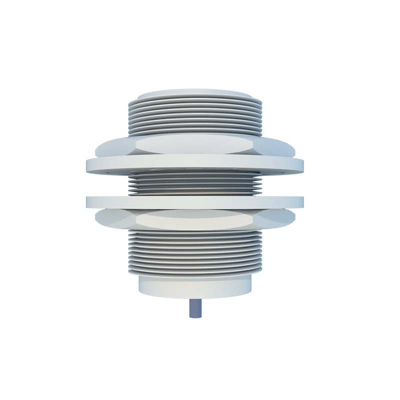
Quality control is integrated throughout the process. Dimensional checks using Coordinate Measuring Machines (CMM) verify critical features. Environmental stress testing, such as thermal shock cycling and humidity exposure, validates the housing's ability to protect the internal electronics. Finally, functional testing of the assembled sensor ensures that the molded housing does not interfere with the electromagnetic field for inductive types or the capacitive field for capacitive types, guaranteeing the specified sensing range and repeatability. By mastering these injection molding specifics—from mold design and material science to process parameter optimization—manufacturers can produce proximity sensor housings that meet the rigorous demands of automation, automotive, and material handling applications, ensuring long-term operational integrity and signal stability.