Laser sensors have become indispensable tools across industries ranging from autonomous vehicles and robotics to precision manufacturing and geospatial surveying. Their ability to provide high-resolution, non-contact distance and dimensional measurements makes them critical for applications demanding accuracy. However, like all measurement instruments, laser sensors are subject to various errors that can degrade their performance. These errors stem from multiple sources, including intrinsic sensor imperfections, environmental influences, and installation misalignments. Consequently, implementing a robust calibration methodology is not optional but a fundamental requirement to ensure data reliability and system integrity.
The calibration process essentially involves comparing the sensor's output against a known reference standard under controlled conditions and deriving correction parameters. The goal is to model and compensate for systematic errors, thereby enhancing measurement accuracy. The complexity of calibration varies significantly based on the sensor type (e.g., 1D distance sensors, 2D LiDAR scanners, 3D profilers) and the required precision.
A primary category of error is systematic bias. This often manifests as a constant offset or a scale factor error. For instance, a sensor might consistently report a distance 0.5 mm shorter than the true value (offset), or its error might increase proportionally with distance (scale error). Calibration for these involves taking multiple measurements at precisely known distances using high-accuracy gauge blocks or linear stages. By plotting the sensor readings against the true values, a linear (or sometimes polynomial) correction function can be established.
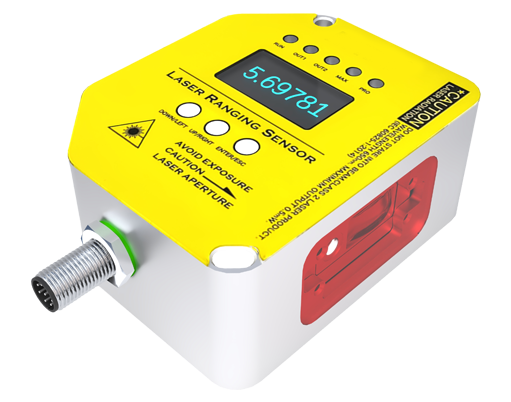
Nonlinearity presents another challenge, where the error does not follow a simple linear relationship. This is common in sensors based on triangulation or time-of-flight principles over their full measurement range. Characterizing nonlinearity requires a dense set of reference points across the entire operational range. The resulting error map or lookup table is then used to correct each raw measurement.
Environmental factors, particularly temperature, have a profound impact. Laser wavelength, detector electronics, and mechanical housing can all drift with temperature changes. Effective calibration must therefore include thermal compensation. This is done by characterizing the sensor's performance in a thermal chamber across its specified operating temperature range. Coefficients are derived to adjust readings based on the sensor's internal or ambient temperature.

For multi-beam or scanning sensors like 2D LiDAR, geometric calibration is paramount. Errors arise from misalignment between the laser's rotational axis and its optical center, non-orthogonality of the scanning plane, and angular encoder inaccuracies. A common geometric calibration method uses a fixed target or pattern (like a checkerboard or precisely positioned vertical edges) observed from multiple known sensor positions. By analyzing the discrepancies between the expected and observed point clouds, parameters for the sensor's internal geometry (e.g., mirror tilt, range offset, angular correction) can be estimated through optimization algorithms like least squares.
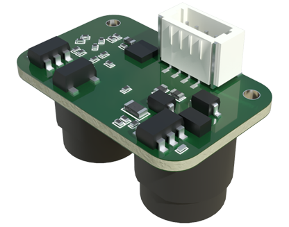
Random noise, while not correctable via deterministic calibration, can be characterized. Assessing the standard deviation of measurements on a stable target provides the repeatability specification. Calibration reports should document this noise level.
The practical workflow for laser sensor calibration typically follows these steps:
1. Preparation: Select a calibration environment that minimizes vibrations, air turbulence, and ambient light interference. Ensure thermal stability.
2. Reference Standards: Use traceable standards (e.g., NIST-calibrated gauge blocks, coordinate measurement machines, or precision linear axes) with an uncertainty at least 3-5 times better than the desired sensor accuracy.
3. Data Acquisition: Systematically collect sensor readings at multiple known reference points, covering the full range and field of view. For thermal calibration, data is collected at various stabilized temperature setpoints.
4. Error Modeling: Fit the data to an appropriate mathematical model. This could be a simple linear regression, a polynomial, a neural network, or a detailed geometric model for scanners.
5. Parameter Generation: Calculate the calibration coefficients or generate the correction lookup table.
6. Validation: Test the calibrated sensor on a *new* set of reference points not used in the parameter calculation. This verifies the calibration's effectiveness and prevents overfitting.
7. Documentation: Create a calibration certificate detailing the procedure, standards used, environmental conditions, correction parameters, and the resulting validated accuracy.
Advanced calibration techniques are emerging with the growth of AI and machine learning. Data-driven approaches can model complex, coupled error behaviors that are difficult to describe with pure physical models. However, the fundamental principle remains: reliance on high-fidelity reference data.
In conclusion, neglecting laser sensor calibration risks propagating significant errors into downstream processes and decisions. A methodical, well-documented calibration routine, tailored to the specific error sources of the sensor and its application, transforms a raw measuring device into a trustworthy metrological instrument. It is the cornerstone for achieving and maintaining the high levels of precision that modern technological systems demand. Regular recalibration is also essential to account for sensor aging and drift over time, ensuring sustained performance throughout the instrument's lifecycle.