Proximity switch sensors are essential components in modern industrial automation, widely used for detecting the presence or absence of objects without physical contact. Their performance and reliability heavily depend on proper wiring configurations, which vary based on sensor type, application requirements, and electrical standards. This article delves into the common wiring systems for proximity sensors, explaining their principles, advantages, and typical use cases.
Proximity sensors primarily operate on inductive, capacitive, or magnetic principles, with inductive sensors being the most prevalent in industrial settings. These sensors detect metallic objects by generating an electromagnetic field, and their wiring configurations are categorized into two-wire, three-wire, and four-wire systems. Each system has distinct characteristics that influence installation, functionality, and compatibility with control systems.
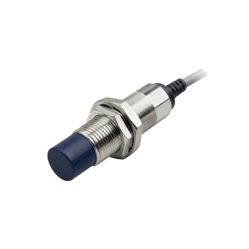
The two-wire configuration is the simplest form, where the sensor is connected in series with the load and power supply. This design reduces wiring complexity and cost, making it suitable for basic applications like conveyor belt monitoring or simple machine controls. However, two-wire sensors often have higher residual current and voltage drop, which can limit their use in precision-sensitive circuits. They are commonly found in AC-powered systems, where their straightforward setup aligns with standard electrical practices.
Three-wire sensors are the industry standard for DC applications, offering improved performance and flexibility. They consist of separate wires for power supply, ground, and output signal. This separation minimizes interference and allows for lower residual current, enhancing detection accuracy. Three-wire sensors come in two output types: NPN (sinking) and PNP (sourcing). NPN sensors switch the negative side of the load, while PNP sensors switch the positive side, with the choice depending on the control system's design. These sensors are ideal for complex automation tasks, such as robotic assembly lines or packaging machinery, where reliable signal transmission is critical.
Four-wire sensors integrate dual output channels, typically combining both NPN and PNP outputs in a single device. This configuration provides versatility for interfacing with diverse control units, enabling simultaneous control of multiple circuits. Four-wire sensors are used in advanced applications requiring redundancy or multi-point detection, like safety systems or high-speed production lines. Their wiring, though more intricate, supports enhanced functionality and system integration.
When selecting a wiring configuration, engineers must consider factors such as power supply compatibility, load requirements, and environmental conditions. For instance, in hazardous areas, intrinsically safe wiring with proper grounding is crucial to prevent sparks. Additionally, adherence to international standards like IEC 60947-5-2 ensures safety and interoperability. Proper installation practices, including using shielded cables and avoiding parallel runs with high-voltage lines, reduce electromagnetic interference and extend sensor lifespan.
In summary, the choice of proximity sensor wiring—whether two-wire, three-wire, or four-wire—impacts system efficiency, cost, and reliability. By understanding these configurations, engineers can optimize sensor performance for specific industrial needs, from simple object detection to sophisticated automation processes. As technology evolves, smart sensors with integrated communication protocols (e.g., IO-Link) are emerging, offering digital wiring options that simplify setup and diagnostics, paving the way for Industry 4.0 applications.