Laser displacement sensors are critical components in modern industrial automation, offering non-contact, high-precision measurement for applications ranging from quality control to robotic guidance. Proper wiring and installation are paramount to ensuring optimal sensor performance, accuracy, and long-term reliability. This guide details the essential steps and considerations for correctly connecting and setting up a laser displacement sensor.
Most laser displacement sensors operate on a low-voltage DC power supply, typically within the range of 12-24 VDC. The first step is always to consult the manufacturer's datasheet for the specific model's electrical requirements, including voltage, current consumption, and polarity. Incorrect power supply connection is a leading cause of sensor failure. Standard wiring involves three primary connections: the power supply lines (V+ and V- or 0V), and the output signal line. Many industrial sensors feature a detachable connector, often a ruggedized M8 or M12 connector, which simplifies wiring and maintenance. The cable shield must be properly grounded at the controller or power supply end to minimize electromagnetic interference (EMI), which can severely distort measurement signals.
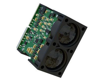
The output configuration is a crucial aspect of wiring. Common output types include analog (e.g., 0-10V, 4-20mA), digital (e.g., NPN/PNP open collector, push-pull), and serial communication (e.g., RS-422, Ethernet/IP). For analog outputs, connect the output wire to the corresponding analog input module on your PLC or controller. Ensure the input impedance matches the sensor's specifications. For digital (switch) outputs, the wiring differs between NPN (sinking) and PNP (sourcing) types. An NPN output switches the negative (0V) line, meaning the load (e.g., PLC input) must be connected between the sensor's output terminal and the positive supply. Conversely, a PNP output switches the positive voltage line. Mismatching these with your controller's input type will result in no signal transmission. Always verify the sensor's output circuit diagram.
For sensors with multiple functions—such as teach-in inputs, alarm outputs, or synchronization (Sync) inputs for multi-sensor setups—additional wiring is necessary. These discrete I/O lines are typically connected to digital I/O points on a controller. Use separate, shielded cables for these signals if they run parallel to power lines to prevent crosstalk. When daisy-chaining multiple sensors for synchronized operation via a Sync line, follow the manufacturer's topology recommendations precisely to avoid timing errors.
Installation considerations are intrinsically linked to electrical performance. Securely mount the sensor using the provided brackets, ensuring it is mechanically stable and free from vibration. The sensing path must be clear of obstructions like dust, steam, or intense ambient light, which can interfere with the laser beam. Maintain the specified sensing distance and ensure the target surface is within the sensor's spot size and reflectivity parameters. A highly reflective or transparent target may require special settings or a different sensor model. After wiring, power on the system and use the sensor's built-in indicators (often LEDs) to verify operational status. Most sensors feature a teach mode or software interface for calibrating the measurement range and setting output scaling.
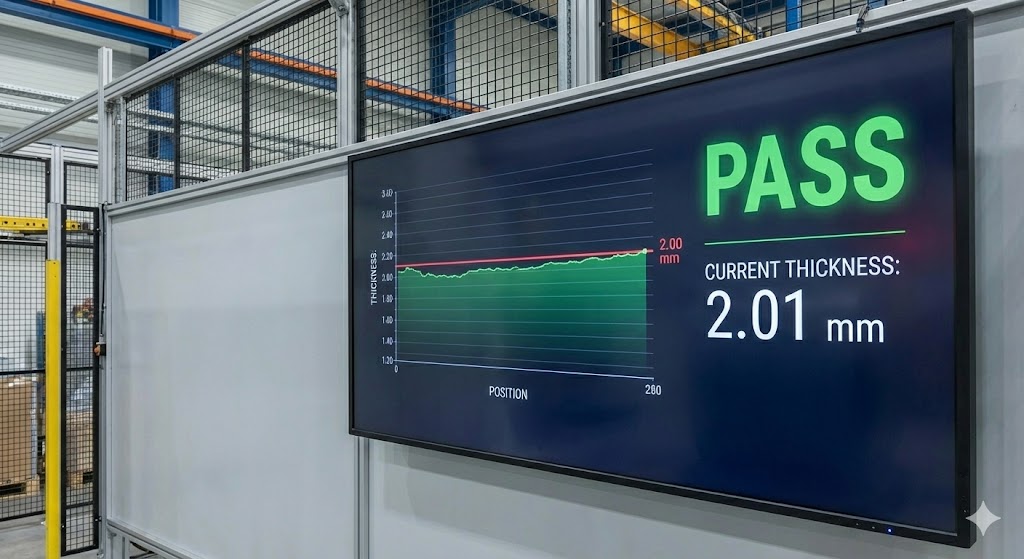
Finally, implement thorough testing under actual operating conditions. Monitor the output signal for stability and noise. Use an oscilloscope to check for clean transitions on digital outputs or a stable voltage/current level on analog outputs. Document the wiring scheme and settings for future maintenance. Adherence to these wiring and installation protocols maximizes measurement precision, protects your investment, and ensures seamless integration into automated systems, from semiconductor fabrication to automotive assembly lines.