Proximity sensors are indispensable components in modern industrial automation, providing non-contact detection of metallic or non-metallic objects. Understanding their wiring diagrams is crucial for ensuring reliable operation, safety, and system integration. This guide delves into the standard wiring configurations, key considerations, and practical insights for engineers and technicians working with these devices.
A typical proximity sensor features three or four wires, corresponding to its power supply, output signal, and ground. The most common types are 3-wire DC sensors and 2-wire AC/DC sensors, with 4-wire models often providing both Normally Open (NO) and Normally Closed (NC) output signals. For a standard 3-wire DC inductive proximity sensor (commonly used for metal detection), the wiring is as follows: The brown wire connects to the positive DC supply voltage (typically 10-30V DC), the blue wire connects to the negative DC supply (0V or common), and the black wire is the switched output signal. When a target enters the sensor's detection range, the black wire either switches to supply voltage (for a PNP, sourcing output) or switches to ground (for an NPN, sinking output). The choice between PNP and NPN is fundamental and depends on the control system's input module (e.g., PLC). PNP wiring, where the output provides positive voltage, is prevalent in Europe and for many PLC sinking inputs. NPN wiring, where the output provides a path to ground, is common in Asia and for PLC sourcing inputs. Miswiring these outputs can lead to malfunction or damage.
For 2-wire AC sensors, wiring is simpler: one wire connects to the AC line voltage (e.g., 120V AC), and the other wire connects to the load. These sensors act as switches in series with the load. A critical factor here is the residual current or leakage current when the sensor is off, which must be considered to prevent unintended activation of sensitive loads. Four-wire sensors combine PNP and NPN outputs, offering wiring flexibility for different control logic requirements, often with a black (NO) wire and a white (NC) wire alongside the standard brown and blue power wires.
When interpreting or creating a wiring diagram, several best practices must be followed. First, always refer to the manufacturer's datasheet for the specific model's pinout, voltage ratings, and output characteristics. Second, implement proper circuit protection. A fuse (1-2A) in the power supply line is recommended to protect against short circuits. For DC sensors, adding a protective diode (like a flyback diode) across the load (especially inductive loads like relays) suppresses voltage spikes that can damage the sensor's output transistor. Third, consider cable routing. Keep sensor cables away from high-voltage power lines and motor drives to prevent electromagnetic interference (EMI), which can cause erratic switching. Using shielded cables with the shield grounded at the control panel end is advisable in electrically noisy environments. Fourth, pay attention to grounding. Ensure a solid, low-impedance ground connection for the blue wire (0V) in DC systems to maintain signal integrity.
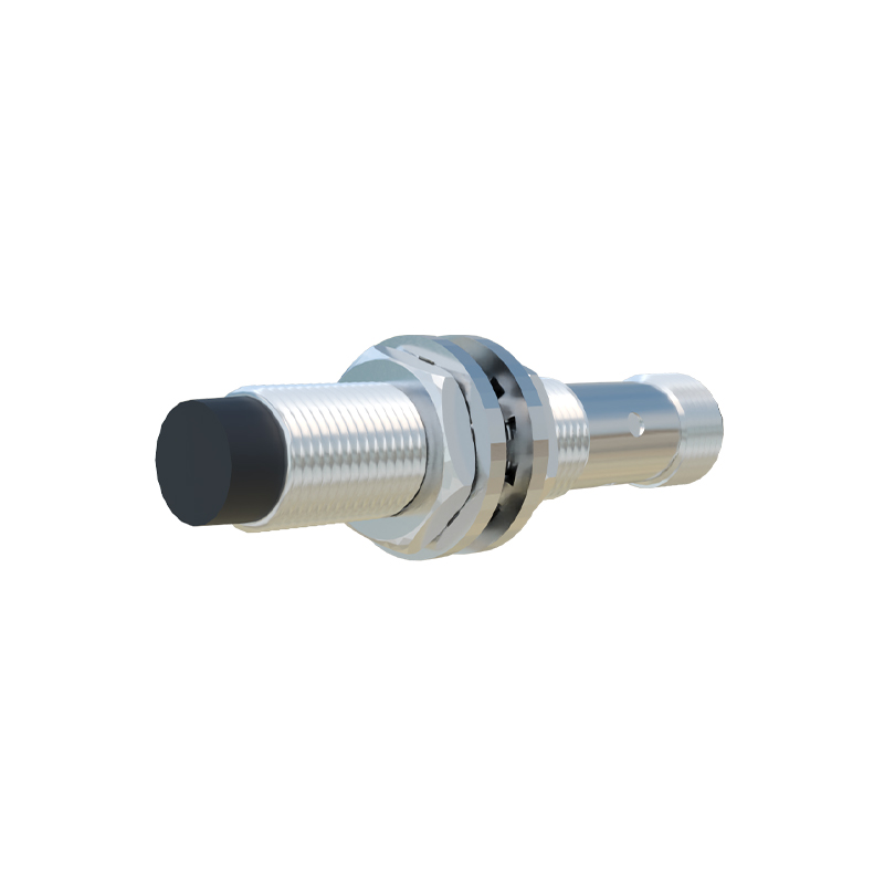
A practical wiring example for integrating a PNP inductive sensor with a PLC digital input module would involve: connecting the brown wire to +24V DC, the blue wire to the PLC's common (0V), and the black wire to the specific PLC input terminal. The PLC input, configured as a sinking input, completes the circuit to ground internally. For an NPN sensor with the same PLC, the wiring changes: the brown wire still goes to +24V, the blue wire to 0V, but the black (NPN output) wire connects to the PLC input. However, the PLC common for the input module must then be connected to +24V, configuring it as a sourcing input to receive the ground signal from the sensor. This highlights the interdependence of sensor wiring and controller configuration.
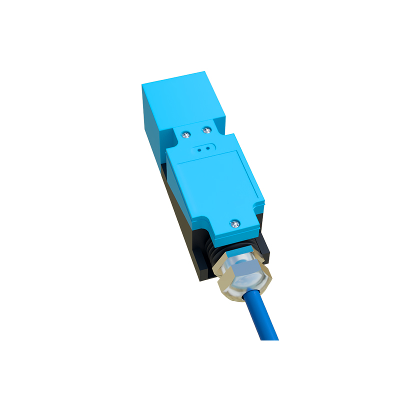
Troubleshooting often starts at the wiring. Common issues include no output signal, intermittent operation, or sensor damage. Use a multimeter to verify power supply voltage at the sensor's terminals (between brown and blue). Check the output signal (black wire) voltage relative to blue (0V) when a target is presented. For a PNP sensor, it should jump from near 0V to near supply voltage. Ensure the load (PLC input, relay coil) is within the sensor's maximum current rating. Also, verify the sensing distance and that the correct target material and size are used, as these factors affect electrical performance.
In conclusion, mastering proximity sensor wiring diagrams is not merely about connecting colored wires. It requires a systematic understanding of electrical principles, sensor specifications, and the control system architecture. Adhering to standardized color codes, implementing protective measures, and methodically verifying connections will ensure robust, fail-safe operation in demanding industrial