Proximity sensors are essential components in industrial automation, offering non-contact detection of metallic or non-metallic objects. Proper wiring is critical to ensure reliable operation and system safety. This guide provides a comprehensive overview of proximity sensor wiring diagrams, covering various types, configurations, and practical applications.
Types of Proximity Sensors and Their Wiring:
1. Inductive Proximity Sensors (for metallic objects):
- Two-wire AC/DC sensors: Connect in series with the load. Brown wire (L+/+) to positive supply, blue wire (L-/-) to load, then to negative supply. Ensure voltage and current ratings match.
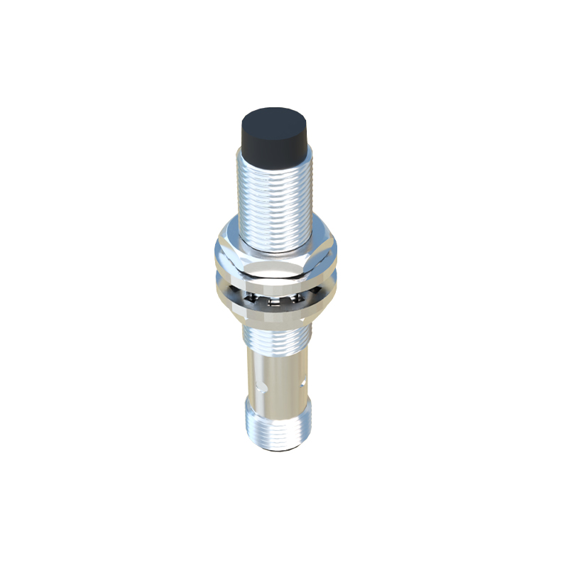
- Three-wire DC sensors: Brown wire to DC+, blue wire to DC-, black wire as output signal. NPN type sinks current to ground; PNP type sources current from positive.
- Four-wire sensors: Additional wire for dual outputs (e.g., NO+NC) or diagnostic functions.
2. Capacitive Proximity Sensors (for all materials):
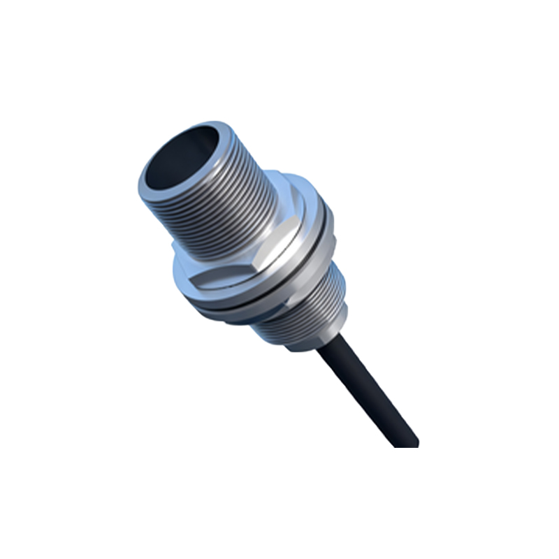
- Similar wiring to inductive types but with sensitivity adjustment. Typically three-wire: brown (power), blue (ground), black (output). Shielded cables recommended for noise reduction.
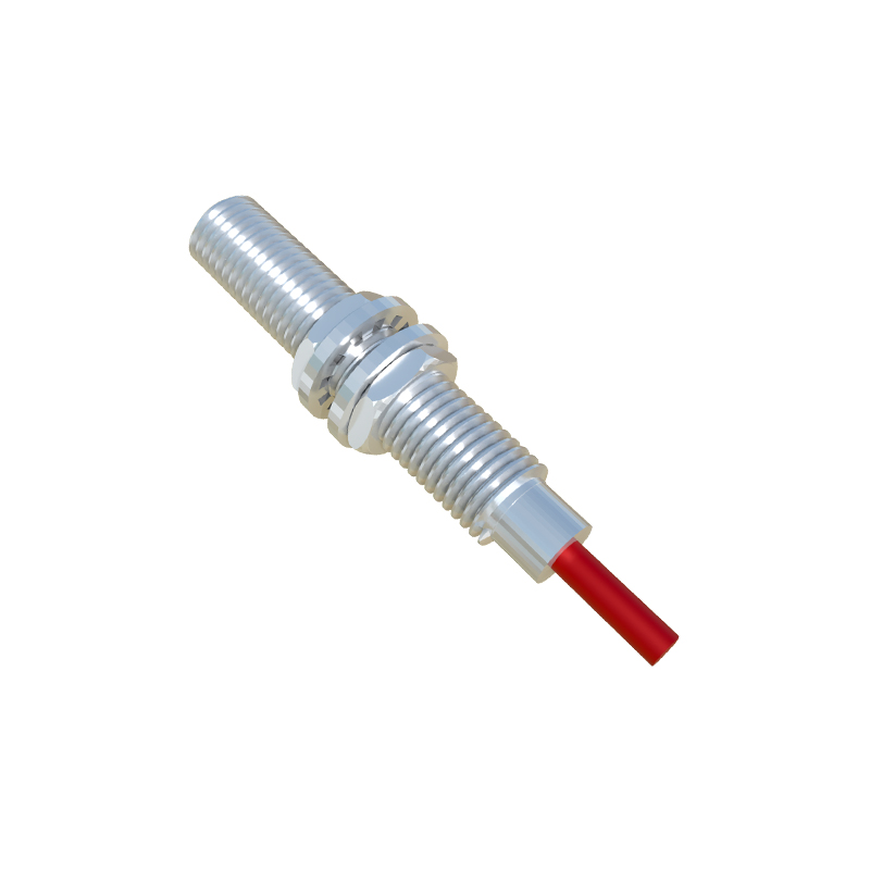
3. Ultrasonic and Photoelectric Sensors:
- Often four-wire: two for power (brown/blue), two for output (black/white). Some models include analog outputs (0-10V/4-20mA) for distance measurement.
Wiring Diagrams Explained:
- DC Two-Wire Sensor: Connect brown wire to positive terminal, blue wire to negative terminal via load (relay/PLC input). Polarity must be observed.
- DC Three-Wire NPN: Brown to +24V, blue to 0V, black to PLC input. Load connects between black wire and +24V.
- DC Three-Wire PNP: Brown to +24V, blue to 0V, black to PLC input. Load connects between black wire and 0V.
- AC Two-Wire: Connect in series with AC load (110-230V). No polarity concern, but ensure insulation ratings.
Key Wiring Practices:
1. Always disconnect power before wiring.
2. Use twisted-pair or shielded cables for long runs (>10m) to prevent EMI.
3. Install surge suppressors for inductive loads (relays/solenoids).
4. Follow manufacturer’s datasheet for voltage ranges (10-30V DC or 20-250V AC).
5. Ground shielding to earth ground at one end to avoid ground loops.
Common Applications and Configurations:
- Machine Safety: Interlock switches wired to safety relays.
- Conveyor Systems: Multiple sensors daisy-chained to PLC inputs.
- Liquid Level Control: Capacitive sensors with relay outputs for pump control.
- High-Speed Counting: NPN sensors with fast-response outputs (<1ms) to counters.
Troubleshooting Tips:
- No Output: Check power supply, wiring polarity, and sensor detection range.
- Intermittent Operation: Inspect for loose connections, voltage drops, or environmental interference.
- False Triggering: Adjust sensitivity, relocate from metal surfaces, or install ferrite cores on cables.
Advanced Topics:
- IO-Link Sensors: Digital communication wiring includes power (brown/blue), signal (black), and IO-Link (white).
- Analog Output Sensors: Wiring includes power wires plus separate analog output wires (e.g., gray for 4-20mA).
- Explosion-Proof Sensors: Follow hazardous area codes (ATEX/IECEx) for conduit and seal fittings.
Conclusion: Correct wiring ensures optimal performance and longevity of proximity sensors. Always verify diagrams against specific model numbers, as pinouts may vary. Implement routine maintenance checks to prevent downtime in automated systems.