In the realm of industrial automation and precision control, laser inductive sensors are indispensable components. Their ability to detect objects, measure distances, and monitor processes with high accuracy makes them critical for maintaining operational efficiency. However, like all sophisticated electronic devices, they are susceptible to failure. This guide provides a systematic approach to diagnosing and repairing common issues with laser inductive sensors, tailored for electrical engineers and maintenance technicians.
The first step in any repair process is accurate diagnosis. A malfunctioning sensor often manifests through symptoms such as erratic readings, complete failure to detect objects, inconsistent output signals, or physical damage to the housing or lens. Before disassembling the unit, always perform a preliminary check. Verify the power supply voltage against the sensor's specifications. An unstable or incorrect voltage is a frequent culprit. Use a multimeter to confirm that the sensor is receiving the correct DC voltage (commonly 10-30V DC) and that the ground connection is secure.
Next, inspect the physical condition. Examine the sensor's lens for dust, oil, scratches, or condensation. Contamination is the leading cause of degraded performance. Carefully clean the lens using a soft, lint-free cloth and an appropriate optical cleaner. Never use abrasive materials or harsh chemicals. Simultaneously, check the mounting. Vibration or misalignment can cause the sensor to shift, leading to inaccurate detection. Ensure the sensor is firmly mounted and correctly aligned with its target.
If basic checks yield no issues, proceed to signal analysis. Connect the sensor's output to an oscilloscope to observe the signal waveform. A healthy digital output should show clean, sharp transitions between high and low states without excessive noise. An analog output (e.g., 4-20mA or 0-10V) should be stable and proportional to the measured distance or presence. Noise, drift, or a flatlined signal indicate internal problems. For sensors with programmable parameters, use the manufacturer's software or teaching button to verify and reset the sensing range, hysteresis, and output configuration. Corrupted settings can sometimes mimic hardware failure.
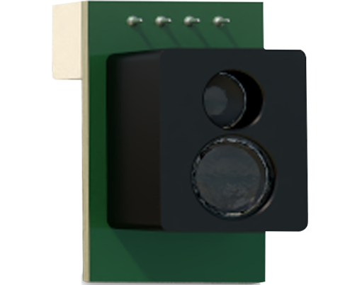
Internal component failure requires careful disassembly. Always disconnect power before opening the sensor housing. Common internal faults include:
1. Laser Diode Degradation: The core emitting component can lose power over time. Test with an optical power meter if available. Replacement requires sourcing an exact or compatible diode and precise realignment—a task often best left to specialized repair services or warrantied replacement.
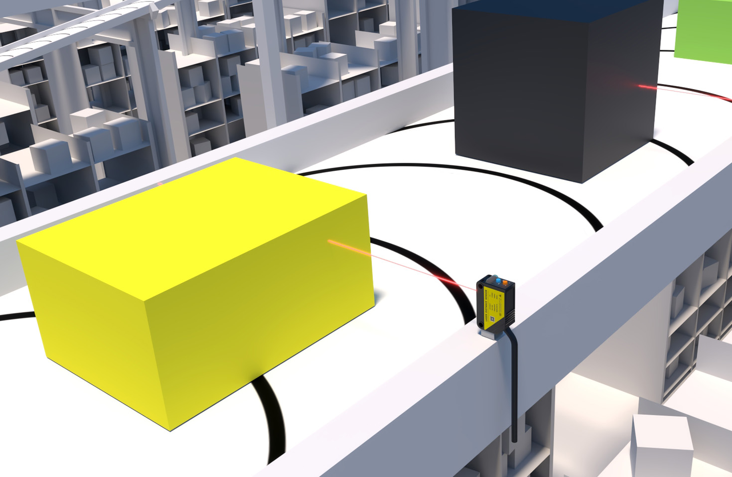
2. Receiver Circuit Issues: The photodiode or receiver IC that detects the reflected light can fail. Check for visible damage, burnt components, or cracked solder joints on the PCB. Use the oscilloscope to trace the signal from the receiver stage through the amplification and conditioning circuits.
3. Power Supply Regulation: Internal voltage regulators or filtering capacitors can fail, especially in harsh environments with temperature extremes. Look for bulging or leaking capacitors on the PCB. Replace them with components of identical specifications (capacitance, voltage rating, and temperature profile).
4. Output Stage Failure: The transistor or IC driving the output signal may be damaged, particularly from inductive load spikes or short circuits. Test output transistors for shorts or opens.
When replacing components, use high-quality, industry-grade parts. Soldering should be precise, avoiding excessive heat that could damage nearby components or the PCB laminate. After any internal repair, recalibration is often necessary. Some sensors have built-in calibration routines; others may require specific distance targets and adjustment potentiometers. Consult the manufacturer's technical manual.
Preventive maintenance is key to minimizing downtime. Implement regular cleaning schedules for lenses. Ensure electrical connections are tight and protected from moisture and corrosion. Use surge protectors or isolation circuits in environments with electrical noise. Monitor operating temperatures to keep them within the sensor's specified range.
Finally, know when to replace rather than repair. If the housing is severely damaged, the core optical assembly is compromised, or the cost and time of repair approach 50-60% of a new unit's price, replacement is the more economical and reliable choice. Keeping a critical spares inventory for essential sensors can drastically reduce production stoppages.
By following this structured approach—from external inspection and signal verification to internal component analysis and post-repair calibration—electrical professionals can effectively restore laser inductive sensor functionality, ensuring continued precision and reliability in automated systems.