In the realm of industrial automation, the seamless integration of field devices with control systems is paramount. Proximity sensors, as non-contact detection devices, are ubiquitous in modern manufacturing, providing critical input on the presence or absence of metallic or non-metallic objects. Programmable Logic Controllers (PLCs) serve as the central nervous system, processing these inputs to execute complex control logic. This article provides a comprehensive, practical guide for electrical engineers on connecting proximity sensors to PLCs, covering fundamental principles, wiring configurations, and best practices.
Understanding Proximity Sensors and PLC Inputs
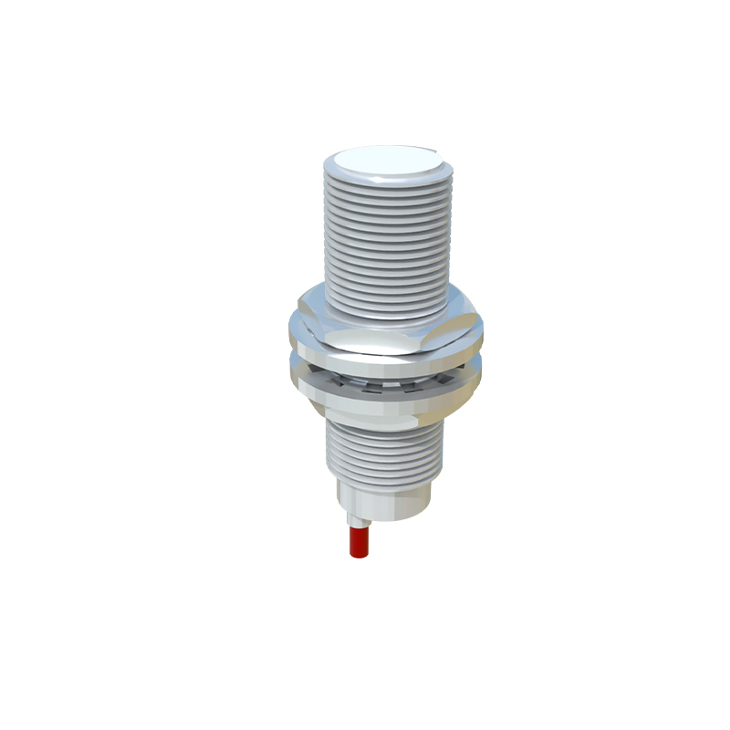
Proximity sensors operate on various principles, including inductive, capacitive, ultrasonic, and photoelectric. Inductive sensors are most common for detecting metallic objects. They generate an electromagnetic field; when a metal target enters this field, it causes a change that is detected by the sensor's internal circuitry, resulting in a switching action. PLCs, on the other hand, are equipped with digital input (DI) modules designed to receive these on/off signals. These inputs are typically categorized as sinking (NPN) or sourcing (PNP), referring to the type of transistor output of the sensor and the corresponding current flow.
Wiring Configurations: Sinking vs. Sourcing
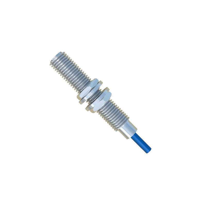
Correct wiring is critical for reliable operation. The configuration depends on the sensor's output type and the PLC input module's compatibility.
1. Sourcing (PNP) Sensor to Sinking PLC Input: This is a common setup. The PNP sensor's output acts as a positive voltage source. The sensor's output wire (usually brown or black) is connected to the PLC's input terminal. The sensor's negative wire (blue) is connected to the DC common (0V) of the power supply, which is also connected to the common terminal of the PLC's input module. When activated, the PNP sensor sources current from its output terminal to the PLC input.
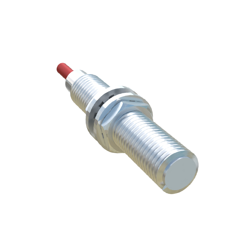
2. Sinking (NPN) Sensor to Sourcing PLC Input: The NPN sensor's output acts as a path to ground (0V). The sensor's output wire is connected to the PLC input. The sensor's positive wire (brown) is connected to the DC positive (+24V) of the power supply, which is also connected to the common terminal of the sourcing PLC input module. When activated, the NPN sensor sinks current from the PLC input to ground.
Mismatching sensor and input types (e.g., PNP sensor to sourcing input) will result in no operation. Always consult the datasheets of both the sensor and the PLC module. Most modern PLC input modules are configurable or designed to accept both types by connecting the common terminal appropriately to +24V or 0V.
Practical Connection Steps
1. Power Supply: Ensure a stable 24V DC power supply (typical for industrial sensors). This supply powers both the sensor and often serves as the reference for the PLC inputs.
2. Sensor Wiring: A standard 3-wire sensor has brown (+V), blue (0V/Common), and black (Output) wires. Connect brown to +24V and blue to 0V. The black output wire connects to the designated PLC input terminal (e.g., I0.0).
3. PLC Input Module Wiring: Connect the common terminal (often labeled "M" or "COM") of the input module. For a sinking input (accepting PNP), connect this common to 0V. For a sourcing input (accepting NPN), connect it to +24V.
4. Completing the Circuit: The sensor's output and the PLC input form the signal circuit. The power supply completes the loop for both the sensor's internal electronics and the signal path.
Considerations and Troubleshooting
Shielded Cables: Use shielded cables in electrically noisy environments. Connect the shield to ground at one end only (usually at the PLC cabinet) to prevent ground loops.
Leakage Current: Solid-state sensors, even in the "off" state, may allow a small leakage current to flow. This can be enough to falsely activate a high-impedance PLC input. A bleeder resistor (typically 10kΩ) wired across the PLC input terminals can dissipate this current.
Inductive Load Protection: While sensors switch PLC inputs (a small load), if driving a relay coil directly, always use a flyback diode across the coil to suppress voltage spikes.
Diagnostics: Use the PLC's programming software to monitor the input status bit. If a sensor fails to trigger, verify: power (24V at sensor), wiring continuity, correct sensor type (PNP