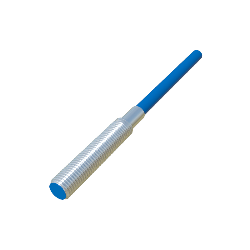
Two-wire proximity sensors are widely used in industrial automation due to their simplicity and cost-effectiveness. Unlike three-wire or four-wire sensors, they integrate the switching element and power supply into a single loop, making installation straightforward. However, proper wiring is crucial for reliable operation and avoiding common pitfalls. This guide provides a comprehensive overview of two-wire proximity sensor wiring, covering principles, circuit design, installation steps, and troubleshooting tips.
Understanding the basic operating principle is essential. A two-wire proximity sensor functions as a switch in series with the load (e.g., a PLC input, relay, or indicator lamp). It requires a DC or AC power supply, depending on the model. The sensor draws a small leakage current (typically under 2 mA) even in the "off" state to power its internal electronics. When a target enters its sensing range, the internal switch closes, allowing full load current to flow. This design eliminates the need for a separate power wire, reducing wiring complexity and material costs.
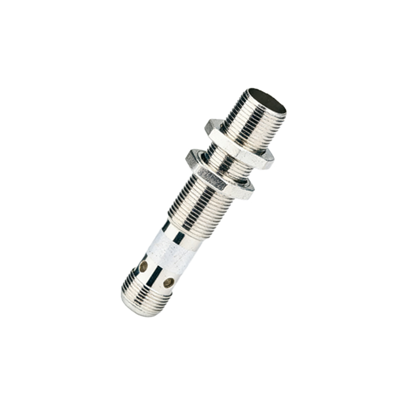
Circuit design considerations are critical for stability. For DC sensors, ensure the power supply voltage matches the sensor's rated voltage (commonly 10-30 V DC). Polarity must be observed: the brown wire (or labeled "+") connects to the positive supply, while the blue wire (or labeled "-") connects to the negative side and the load. The load is then connected between the sensor's blue wire and the supply negative, completing the series circuit. For AC sensors (often 20-250 V AC), wiring is polarity-insensitive, but voltage and frequency (50/60 Hz) specifications must be adhered to. Always check the datasheet for exact ratings.
A key parameter is the residual current or leakage current. In the "off" state, this current may be sufficient to weakly activate some sensitive loads, causing false triggers. To prevent this, ensure the load's minimum operating current is higher than the sensor's leakage current. If using a PLC input, verify its threshold; adding a bleeder resistor in parallel with the load can dissipate leakage current. Additionally, consider voltage drop: the sensor's internal resistance causes a small voltage loss, so the load must operate correctly at the reduced voltage.
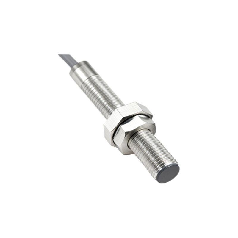
Installation follows a systematic process. First, de-energize the circuit and confirm safety lockout procedures. Strip the sensor wires to the recommended length, typically 7-10 mm. Use crimp connectors or terminal blocks for secure connections. For DC sensors, connect the brown wire to the positive supply terminal and the blue wire to one terminal of the load. Connect the load's other terminal to the supply negative. For AC sensors, connect one sensor wire to the live supply and the other to the load, then link the load to neutral. Secure cables away from high-voltage lines or motors to avoid electromagnetic interference. After wiring, perform a functional test by bringing a target within sensing distance and verifying load activation.
Troubleshooting common issues involves methodical checks. If the sensor fails to activate, measure the supply voltage at the sensor terminals under load to ensure it meets minimum requirements. Check for loose connections or damaged wires. If the load stays on, excessive leakage current might be the cause; test with a higher-wattage load or add a bleeder resistor. False triggering can result from electrical noise; use shielded cables and ground the shield at one end. Also, ensure the sensing face is clean and free from obstructions, and that the target material and size are within specifications. For harsh environments, select sensors with appropriate IP ratings and consider using surge protectors.
In summary, two-wire proximity sensors offer a streamlined solution for many applications, but their performance hinges on correct wiring practices. By adhering to electrical standards, accounting for leakage current, and implementing noise mitigation, engineers can achieve robust and maintenance-free operation. Always consult manufacturer guidelines for specific models, as variations exist in wiring diagrams and technical parameters.