In the realm of industrial automation and machine safety, proximity sensors are ubiquitous, silent sentinels that detect the presence or absence of objects without physical contact. As a seasoned electrical engineer, I often find that a deep understanding of a component's internal architecture is key to optimal selection, troubleshooting, and application. Today, we will perform a detailed teardown analysis of a typical inductive proximity sensor, a common workhorse in factory environments for detecting metallic targets.
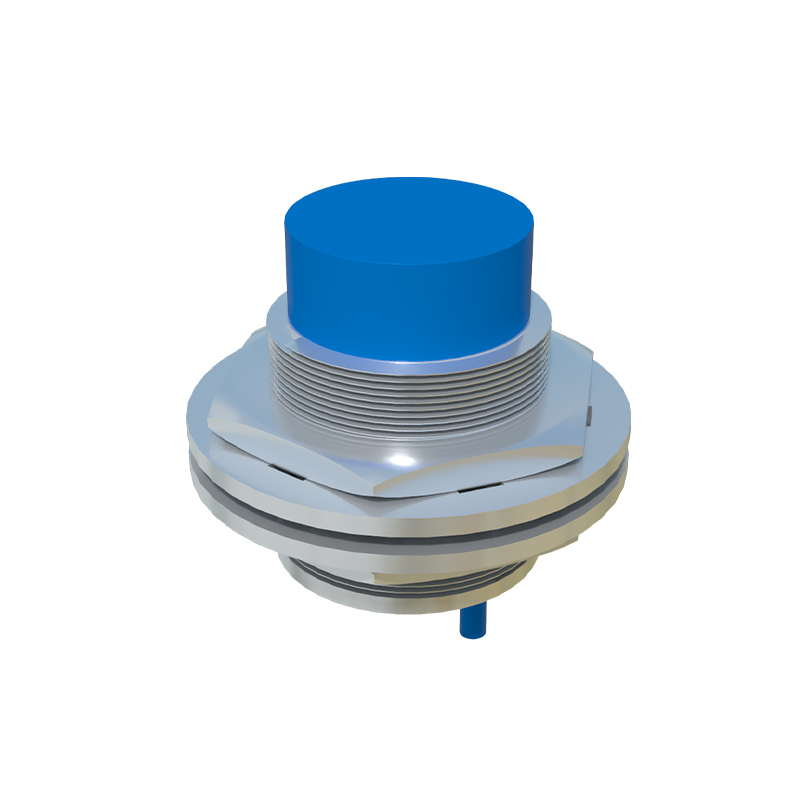
Our subject is a standard cylindrical, shielded, DC 3-wire NPN normally-open inductive sensor. The external housing is a robust, threaded metal barrel, typically made of nickel-plated brass or stainless steel, providing environmental protection (IP67 rating) and mechanical strength. The sensing face is a wear-resistant polymer disc, often PBT or similar, which allows the electromagnetic field to emanate while protecting the internal coil.
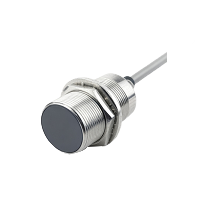
The disassembly begins by carefully removing the polymer sensing face. This often reveals a ferrite core assembly. This core is crucial; it's a high-permeability material that concentrates the oscillating magnetic field generated by the coil directly in front of the sensor. The coil itself, fine-gauge copper wire wound precisely around the ferrite core, is the heart of the sensor. It forms part of an LC oscillator circuit. In the absence of a metallic target, this oscillator runs at a specific resonant frequency.
The printed circuit board (PCB) is compact and densely packed. Key components include:
1. The Oscillator IC/Circuitry: This generates the high-frequency alternating current (typically 100 kHz to 1 MHz) through the coil.
2. The Demodulator and Trigger Circuit: When a conductive metal target enters the sensing field, eddy currents are induced in the target. This energy loss dampens the oscillator's amplitude or changes its frequency. This change is detected by the demodulator.
3. The Output Stage: The trigger circuit activates the output switch. In our NPN sensor, this is a power transistor (often a MOSFET for switching speed and efficiency) that sinks current to ground. The PCB will also host voltage regulation, reverse polarity protection diodes, and often a status LED indicator.
4. EMI/RFI Suppression Components: Ferrite beads and small capacitors are strategically placed to ensure electromagnetic compatibility, preventing the sensor from interfering with other equipment or being disrupted by external noise—a critical consideration in industrial settings.
The potting compound is a significant finding. After removing the PCB assembly, we see the entire internal cavity is filled with a rigid, epoxy-based potting material. This is not merely for structural support. It serves vital functions: it permanently secures the ferrite core and coil assembly, provides exceptional resistance to vibration and shock, and creates a complete moisture and contaminant barrier, ensuring long-term reliability in harsh conditions. Attempting to repair a potted sensor is generally impractical; the potting is a definitive end-of-life design choice favoring durability over serviceability.
Engineering insights from this teardown are manifold. The shielded design (metal barrel extended to the sensing face's periphery) allows for flush mounting in metal, reducing installation constraints. The choice of ferrite core material and coil geometry directly impacts the sensing range and frequency response. The quality of the output transistor and its heatsinking (often via the metal housing) determines the switching capacity and longevity under load. The robustness of the potting compound directly correlates with the IP rating and mean time between failures (MTBF).
Understanding these internal elements empowers engineers. When selecting a sensor, one can better appreciate specifications like switching frequency, hysteresis, and temperature drift. For troubleshooting, knowing the signal path—from coil oscillation to transistor switching—guides effective diagnostic procedures with an oscilloscope. It also highlights why these devices, while seemingly simple, are precision-engineered components where cost-cutting can severely impact performance in demanding applications. This internal complexity, hidden within a rugged shell, is what makes the modern inductive proximity sensor a model of reliability in industrial control systems.