Proximity sensors are indispensable components in modern industrial automation, playing a critical role in object detection, position sensing, and process control without physical contact. Their reliable operation hinges on correct wiring, a fundamental yet sometimes overlooked aspect of installation. This guide details standard wiring methods for the most common types of proximity sensors—Inductive, Capacitive, and Photoelectric—focusing on 2-wire, 3-wire, and 4-wire configurations, while emphasizing safety and best practices.
Understanding the core types is the first step. Inductive sensors detect metallic objects using an electromagnetic field. Capacitive sensors can detect both metallic and non-metallic materials by sensing changes in capacitance. Photoelectric sensors use a light beam, typically infrared, to detect the presence or absence of an object. Each type shares common wiring principles but may have specific requirements.
The 2-wire AC/DC sensor is the simplest to connect, functioning similarly to a switch in series with the load. It has only two wires: one for power (Line/L+) and one for the load (Load). The sensor itself consumes a small "quiescent" current even when off, which must be considered to ensure the load receives sufficient voltage. A key advantage is easy replacement of mechanical limit switches, but voltage drop across the sensor can be a limitation for sensitive loads.
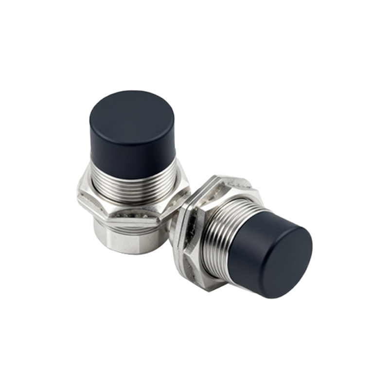
The 3-wire DC sensor is the industry standard for DC applications due to its superior performance. It features three distinct wires: Brown (or Red) for DC supply positive (+V), Blue for DC supply negative (0V/Common), and Black (or sometimes White) for the switched output signal. There are two output types: NPN (Sinking) and PNP (Sourcing). An NPN sensor switches the Black output wire to the negative (0V) rail, "sinking" current to ground. Conversely, a PNP sensor switches the Black output wire to the positive (+V) rail, "sourcing" current to the load. Confusing these is a common error; always verify the sensor's datasheet and the input type of your controller (PLC, relay). The load is connected between the Black wire and the opposite supply rail (for NPN: load between Black and +V; for PPN: load between Black and 0V).
The 4-wire DC sensor typically provides two complementary outputs, often one NPN (Normally Open) and one PNP (Normally Closed), or two independent channels. This configuration offers wiring flexibility for controlling different circuit polarities or providing a backup signal. Wiring follows the same color conventions, with the additional output wire often being White. Always reference the manufacturer's diagram.
For AC-powered 3-wire sensors, the standard is: Brown for Line (L+), Blue for Neutral (N), and Black for the switched output to the load. The load connects between the Black wire and the Neutral (Blue) wire.
Shielded cable is highly recommended, especially in environments with significant electromagnetic interference (EMI) from motors, drives, or welding equipment. Connect the cable shield to a functional earth ground at the controller end only, avoiding a "pig-tail" connection, to ensure effective noise immunity.
Critical safety and performance practices include:
1. Always De-energize: Power down the circuit before connecting or disconnecting wires.
2. Consult the Datasheet: Wire colors and functions can vary by manufacturer and region. The printed label or documentation is the ultimate authority.
3. Correct Polarity: Incorrect DC polarity will damage the sensor.
4. Load Compatibility: Ensure the sensor's output current and voltage ratings exceed the requirements of the connected load (relay, PLC input, lamp).
5. Short-Circuit Protection: Many modern sensors have built-in protection, but external fusing per specifications is a wise precaution.
6. Avoid Inductive Load Spikes: When controlling relays or solenoids, use a suppression device (flyback diode for DC, RC snubber for AC) across the load to protect the sensor's output transistor from voltage transients.
7. Proper Grounding: Ensure a solid, low-impedance earth ground connection for the sensor's housing (if metallic) and the system common.
Testing after installation is straightforward. Use a multimeter to check for the correct supply voltage at the sensor terminals. Then, trigger the sensor by introducing a target object. For a 3-wire NPN sensor, the voltage between the Black (output) and Blue (0V) wires should switch from high (near +V) to low (near 0V) when activated. For a PNP sensor, it will switch from low (near 0V) to high (near +V).
In summary