Proximity sensors are indispensable components in modern industrial automation, serving as non-contact detection devices that identify the presence or absence of objects within their sensing range. Understanding what proximity sensors primarily connect to is crucial for ensuring reliable system integration, optimal performance, and operational safety. This guide delves into the core wiring and connection principles for various types of proximity sensors, including inductive, capacitive, and photoelectric models, tailored for industry professionals.
Fundamentally, a proximity sensor connects to two primary systems: a power supply and a load or controller. The specific connections depend on the sensor's output type—typically categorized as NPN (sinking) or PNP (sourcing) for DC sensors, and 2-wire or 3-wire AC/DC variants. For a standard 3-wire DC sensor, the three essential wires are the brown wire (positive supply, +V), the blue wire (common negative or 0V), and the black wire (switched output signal). The brown wire connects to the positive terminal of the DC power source, while the blue wire connects to the negative terminal. The critical black output wire is then connected to the load. In a PNP configuration, this output provides positive voltage to the load, which is subsequently connected to ground. Conversely, in an NPN configuration, the output provides a path to ground for the load, which is connected to the positive supply.
The load itself is what the sensor ultimately controls or signals. This is most frequently a programmable logic controller (PLC) input module, a relay coil, a solenoid valve, an indicator lamp, or the input channel of a motor starter. When connecting to a PLC digital input, it is imperative to match the sensor's output type (PNP or NPN) with the PLC input's sinking or sourcing specification to avoid malfunction or damage. For instance, a PNP sensor should connect to a sinking PLC input. The load is placed in series between the sensor's output wire and the opposite power rail.
For 2-wire AC or DC sensors, wiring is simpler as they have only two terminals that are connected in series with both the power supply and the load. They function like a switch, but attention must be paid to the minimum holding current to ensure proper operation and avoid leakage current issues that might keep a relay energized.
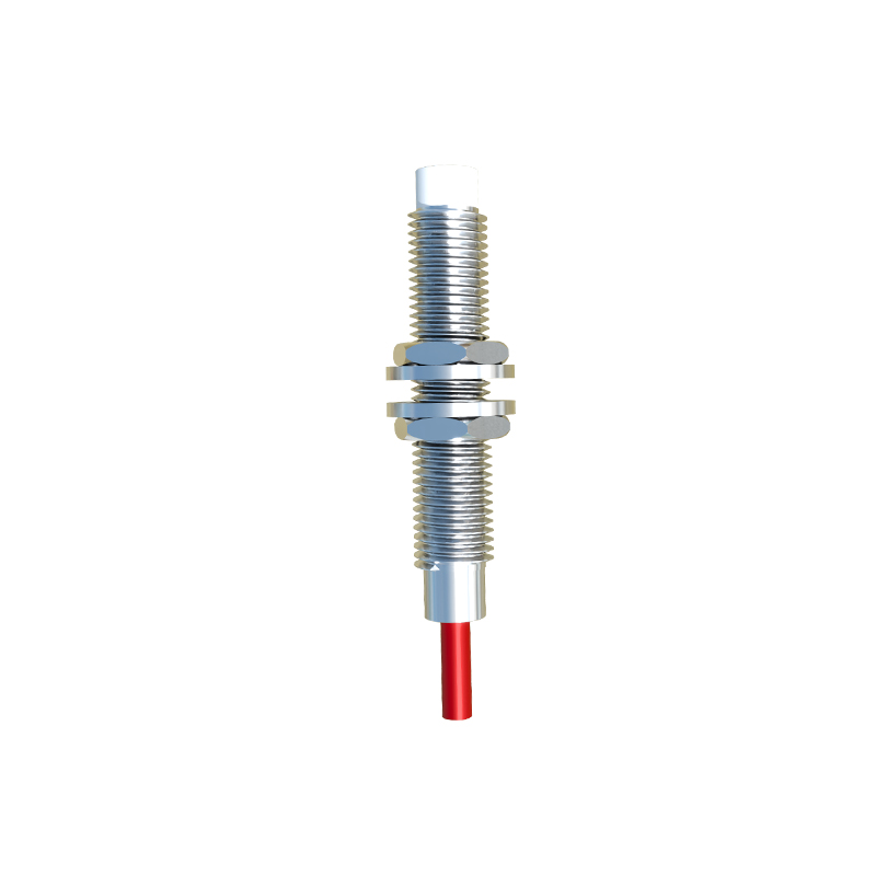
Beyond basic power and load, proximity sensors often require consideration for shielding and grounding. The shield wire, if present, should be grounded at one end only, typically at the control panel, to minimize electrical noise interference, especially in environments with variable frequency drives or heavy machinery. Additionally, some advanced sensors feature complementary outputs (NO and NC), analog outputs (4-20mA, 0-10V), or IO-Link digital communication interfaces. For analog sensors, the connection involves power wires plus the signal wire to an analog input module. IO-Link sensors require a point-to-point connection to an IO-Link master for bidirectional data exchange, enabling parameter setting and advanced diagnostics.
Proper connection also involves protective measures. Installing surge suppressors or flyback diodes across inductive loads (like relay coils) is essential to protect the sensor's solid-state output from voltage spikes generated when the load is de-energized. Always adhere to the manufacturer's datasheet for voltage, current, and wiring specifications. Incorrect wiring can lead to sensor failure, erratic operation, or permanent damage to connected controllers. A systematic approach—verifying power requirements, identifying output type, selecting appropriate cable gauges, and implementing noise protection—forms the bedrock of a robust and maintenance-free proximity sensor installation in any industrial setting.