Proximity sensors are indispensable components in modern industrial automation, offering non-contact detection of metallic or non-metallic objects. Understanding their wiring configurations is crucial for ensuring reliable operation, safety, and system integration. This guide provides a comprehensive overview of standard proximity sensor wiring diagrams, tailored for engineers and technicians in the electrical and automation fields.
Proximity sensors are typically categorized into two primary types based on their output configuration: 2-wire, 3-wire, and occasionally 4-wire sensors. Each type has distinct wiring requirements and applications.
1. 2-Wire Proximity Sensor Wiring
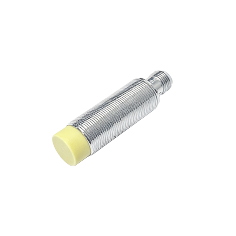
The 2-wire sensor is the simplest type, functioning similarly to a mechanical switch. It connects in series with the load and the power supply. One wire is connected to the positive voltage supply (often labeled as brown wire according to international standards like IEC), and the other wire (usually blue) is connected to the load, which then connects to the power supply's negative or neutral line. A key consideration is the voltage drop across the sensor when conducting, which must be accounted for in low-voltage circuits. These sensors are commonly used in basic on/off control applications where simplicity and cost are priorities.
2. 3-Wire Proximity Sensor Wiring
This is the most prevalent configuration in industrial settings due to its separate power and output lines, offering better performance and flexibility. Three-wire sensors come in two output types: NPN (sinking) and PNP (sourcing).
- NPN Wiring Diagram: The brown wire connects to the positive supply voltage (e.g., +24V DC). The blue wire connects to the common ground (0V). The black wire is the output signal line. In an NPN sensor, the output transistor switches the load to ground. Thus, the load is connected between the positive supply and the black output wire. When the sensor detects an object, the black wire is pulled to ground, completing the circuit and activating the load.
- PNP Wiring Diagram: The brown wire again connects to positive voltage, and the blue to ground. However, in a PNP sensor, the black output wire switches the positive voltage. The load is connected between the black wire and ground. Upon detection, the output provides positive voltage to the load.
Choosing between NPN and PNP often depends on the control system's input card configuration (sinking vs. sourcing inputs).
3. 4-Wire Proximity Sensor Wiring
Four-wire sensors typically provide two complementary outputs (e.g., one NPN and one PNP) or a dual-channel configuration for enhanced functionality like logic control. The wiring follows the principles of 3-wire sensors but includes an additional output wire (often white or gray). The standard color code is brown (+V), blue (0V), black (output 1), and white (output 2). These are used in more complex circuits requiring multiple signal states.
Key Wiring Practices and Safety Considerations:
- Power Supply: Always use the correct DC voltage (commonly 10-30V DC) as specified. Incorrect voltage can damage the sensor.
- Shielded Cables: In environments with significant electromagnetic interference (EMI), use shielded cables. Connect the shield to ground at only one end to prevent ground loops.
- Load Compatibility: Ensure the sensor's output current rating is not exceeded by the connected load (e.g., a PLC input, relay coil). Use an external relay for high-current loads.
- Short-Circuit Protection: Many modern sensors include built-in protection, but external fuses or circuit breakers are recommended for the supply line.
- Wiring Diagram Symbols: Familiarize yourself with standard IEC symbols: the sensor is often represented by a diamond shape with markings for type (e.g., "LJ" for inductive) and output.
Interfacing with Programmable Logic Controllers (PLCs):
When connecting to a PLC digital input module, first identify whether the module is designed for sinking (common +24V) or sourcing (common 0V) inputs. For a sinking input module, use a PNP sensor. For a sourcing input module, use an NPN sensor. Incorrect pairing will result in no signal detection. Always refer to both the sensor and PLC manuals for terminal designations.
Troubleshooting Common Wiring Issues:
- No Output Signal: Check power supply polarity and voltage. Verify the load is correctly connected and within specifications. Ensure the sensing object is within the rated detection range.
- Intermittent Operation: Look for loose connections, damaged cables, or EMI interference. Check for voltage fluctuations in the supply.
- Sensor Damaged: