In the realm of industrial automation and machine control, proximity sensors are fundamental components that provide critical non-contact detection of objects. Consequently, the term "proximity sensor image" is not a reference to a visual photograph or a camera-like output. Instead, it is a conceptual and functional representation of the sensor's detection field and its operational status within a system. Understanding this "image" is key to proper selection, installation, and troubleshooting.
At its core, a proximity sensor (inductive, capacitive, ultrasonic, or photoelectric) generates a detection field. For an inductive sensor, this is an electromagnetic field; for a capacitive sensor, an electrostatic field; for photoelectric sensors, a beam of light; and for ultrasonic sensors, a cone of sound waves. The "proximity sensor image" refers to the precise shape, size, and sensitivity profile of this active field. It defines the zone within which a target object will be reliably detected. Technical datasheets provide diagrams that are, in essence, the official "image" of the sensor's sensing characteristics. These diagrams show critical parameters such as the rated operating distance (Sn), the assured operating distance (Sa), and the hysteresis zone. They illustrate how the detection field behaves, which is often not a simple, sharp-edged bubble but a gradient of sensitivity.
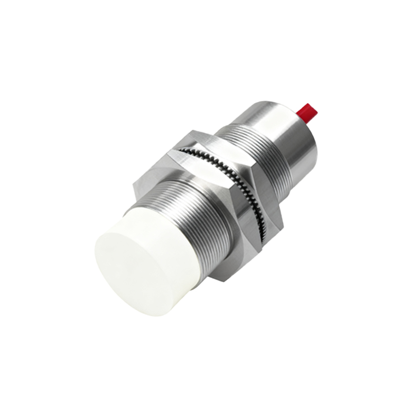
Furthermore, in a broader system context, the "proximity sensor image" extends to its electrical and logical representation. This includes the state of its output signal (e.g., PNP/NPN, NO/NC) as seen on a programmable logic controller (PLC) input module or a diagnostic screen. On a Human-Machine Interface (HMI) or SCADA system, a graphical icon of the sensor may change color (e.g., from gray to green) to indicate the presence or absence of a target. This real-time status indicator is the operational "image" presented to the plant operator or maintenance engineer. It is a virtual representation of the physical sensor's state, crucial for monitoring process flow and identifying faults. For instance, a sensor icon persistently showing "on" when it should be "off" provides an immediate visual clue for a jammed part or a sensor alignment issue.
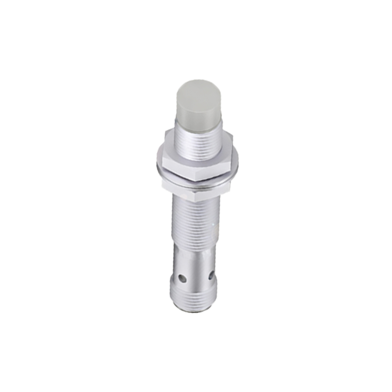
The concept is also vital for integration and safety. When designing a machine layout, engineers must consider the "image" of every sensor's detection field to prevent mutual interference (e.g., two inductive sensors affecting each other) and to ensure the sensor is positioned correctly for the target material, size, and approach direction. Shielding types (shielded vs. unshielded inductive sensors) create different field "images," with shielded sensors having a more focused frontal field and unshielded sensors having a larger lateral field. Choosing incorrectly can lead to missed detections or false triggers.
In diagnostic procedures, technicians often rely on both the physical and system "images." They may use a target (like a metal plate) to verify the physical sensing field matches the datasheet specifications. Simultaneously, they monitor the PLC logic or HMI to confirm the electrical signal corresponds correctly to the physical event. Discrepancy between these two "images" points to a wiring fault, a faulty sensor, or a configuration error in the controller.
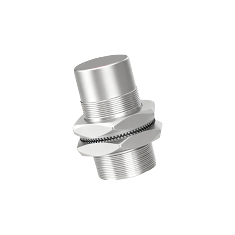
Therefore, for an electrical or automation engineer, interpreting a "proximity sensor image" is a multifaceted skill. It involves reading technical drawings of sensing fields, understanding electrical schematics, and navigating software interfaces. It bridges the gap between the sensor's physical operation in the harsh industrial environment and its role as a data point in a digital control system. A precise understanding of this concept ensures reliable machine operation, reduces downtime, and is fundamental to implementing efficient and safe automated processes. Always consult the manufacturer's specific datasheets for the exact "image" of your sensor, as variations between models and technologies are significant.