In industrial automation and motion control systems, the integration of proximity sensors with buffers is a critical design consideration for ensuring safety, precision, and equipment longevity. A buffer, or shock absorber, is a device used to decelerate moving loads smoothly and absorb kinetic energy at the end of a linear or rotary motion path. The role of a proximity sensor in this context is to detect the position of the moving object as it approaches the buffer, enabling controlled deceleration and providing vital feedback to the control system. This article delves into the technical principles, selection criteria, and application best practices for proximity sensors in buffer systems.
Proximity sensors are non-contact devices that detect the presence or absence of a target object within their sensing field. For buffer applications, the most common types are inductive and magnetic proximity sensors. Inductive sensors are ideal for detecting metallic targets, such as the piston of a hydraulic or pneumatic cylinder nearing its end-of-stroke position where a buffer is mounted. They operate by generating an electromagnetic field; when a metallic object enters this field, it induces eddy currents, causing a change in the sensor's oscillation amplitude, which is then converted into a switching signal. Magnetic sensors, often referred to as reed switches or Hall-effect sensors, are used to detect the position of a permanent magnet typically embedded in the piston of a cylinder. They are highly reliable in dirty or oily environments where optical sensors might fail.
The primary function of the proximity sensor in a buffer system is to provide a signal that triggers a controlled slowdown before the load makes contact with the physical buffer. This is often part of a "slow-down" or "deceleration" zone in automated machinery. For instance, in a high-speed pick-and-place unit or a heavy-duty gantry system, the sensor detects the approaching arm or carriage and signals the drive controller to reduce velocity. This prevents harsh, high-impact collisions with the buffer, reducing mechanical stress, noise, and wear on both the moving components and the buffer itself. It effectively turns a potential crash into a gentle, managed stop.
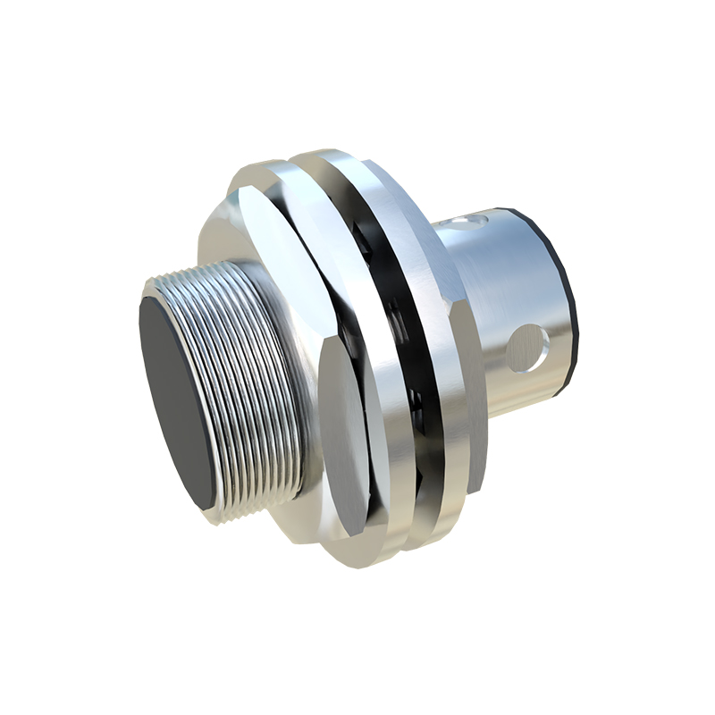
Selecting the right proximity sensor for a buffer application requires careful analysis of several parameters. First, the sensing distance must be chosen correctly. It should be long enough to allow sufficient time and distance for the system to decelerate from its maximum operating speed to a safe impact speed, but not so long that it risks false triggers from other objects in the vicinity. Environmental factors are paramount. Buffers are frequently installed in harsh conditions involving vibration, temperature extremes, coolant, metal chips, and hydraulic fluids. Therefore, sensors with high IP (Ingress Protection) ratings, such as IP67 or IP69K, and robust housing materials like stainless steel or PBT plastic, are essential. The switching frequency must also match the application's speed; a high-speed packaging line requires a sensor with a much faster response time than a slow-moving industrial door.
Electrical characteristics are equally important. Designers must choose between PNP (sourcing) and NPN (sinking) output configurations to match the PLC or controller input. The voltage rating (commonly 10-30V DC) must be compatible with the plant's power supply. For safety-critical applications, such as those involving large inertial loads, using a redundant sensor configuration or a safety-rated proximity sensor with a dual-channel output may be necessary to achieve the required Safety Integrity Level (SIL) or Performance Level (PL).
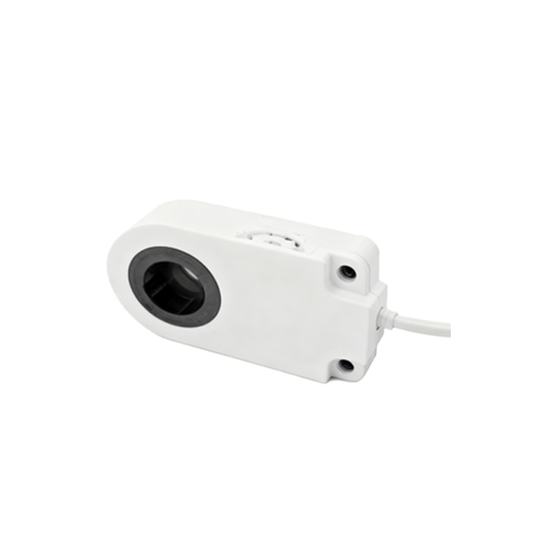
Installation and alignment are often the difference between reliable operation and persistent failure. The sensor must be mounted securely to withstand constant vibration from machine operation and impacts from the buffering process. For inductive sensors, the sensing face must be positioned parallel to the target's approach path at the correct distance. Misalignment can reduce the effective sensing range or cause intermittent signals. For magnetic sensors, the orientation of the magnet's poles relative to the sensor is crucial. Proper shielding should be considered in environments with strong electromagnetic interference from motors or welders.
In advanced motion systems, the proximity sensor's signal is integrated into a broader control logic. It can be used not only to initiate deceleration but also to confirm that the deceleration sequence has been completed successfully, providing a "buffer engaged" status to the machine controller. This feedback loop is vital for predictive maintenance. By monitoring the point at which the sensor is triggered over time, engineers can detect changes in the deceleration profile, which may indicate wear in the buffer's internal damping mechanism or a change in the system's friction, allowing for maintenance before a failure occurs.
In conclusion, proximity sensors are indispensable components in modern buffer systems. They transform a simple mechanical energy-absorption device into an intelligent, feedback-rich element of the motion control ecosystem. By enabling precise, repeatable, and gentle deceleration, they protect capital equipment, enhance process reliability, and contribute to overall operational safety. For engineers designing or maintaining such systems, a