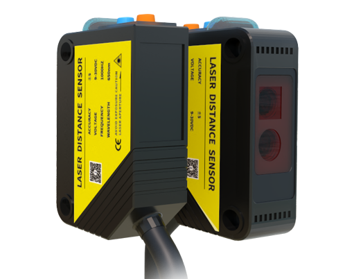
Laser scanning sensors have become integral components in modern engineering applications, ranging from autonomous vehicles and robotics to industrial automation and topographic mapping. For engineering students, designing and implementing a laser scanning sensor system as a course project offers a hands-on opportunity to bridge theoretical knowledge with practical skills. This article outlines a comprehensive approach to developing such a system, focusing on key design considerations, component selection, implementation steps, and real-world testing.
The foundation of any laser scanning sensor project lies in understanding its core principle: using laser beams to measure distance or detect objects by analyzing reflected light. Typically, a laser diode emits a focused beam that strikes a target, and a photodetector captures the return signal. By calculating the time-of-flight or phase shift of the light, the system can determine precise distances. For scanning applications, a rotating mirror or motorized mechanism is often incorporated to sweep the laser across a field of view, enabling 2D or 3D environmental mapping.
In the initial design phase, students should define project objectives based on application needs. For instance, a simple obstacle detection system for a mobile robot may require a scanning angle of 180 degrees and a range of up to 5 meters, while a high-precision mapping project might demand 360-degree coverage with millimeter-level accuracy. Key specifications to consider include scanning speed, resolution, range, power consumption, and environmental robustness. Budget constraints also play a crucial role, as commercial laser sensors can be expensive; hence, many students opt for affordable components like low-cost laser modules, stepper motors, and microcontroller boards.
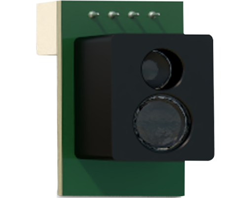
Component selection is critical to the project's success. A typical setup includes a laser emitter (e.g., a 650nm red laser diode), a receiver (such as a phototransistor or avalanche photodiode), a scanning mechanism (like a galvanometer or servo motor), and a processing unit (e.g., Arduino, Raspberry Pi, or STM32 microcontroller). Students must ensure compatibility between parts—for example, matching the laser's wavelength with the detector's sensitivity and selecting a motor with sufficient torque for smooth scanning. Additional elements may include optics for beam shaping, filters to reduce ambient light interference, and encoders for position feedback.
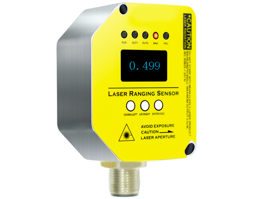
Implementation begins with assembling the hardware. The laser and detector are mounted on a platform attached to the scanning mechanism, which is controlled by the microcontroller. Wiring should follow best practices to minimize noise, especially in signal lines from the photodetector. Power management is essential, as lasers and motors can draw significant current; using regulated power supplies and decoupling capacitors helps prevent voltage drops and erratic behavior. For safety, always incorporate measures like laser safety goggles and enclosures, as even low-power lasers can pose eye hazards.
Software development involves programming the microcontroller to coordinate scanning and data acquisition. Algorithms for distance calculation—such as time-of-flight or triangulation methods—must be implemented efficiently to handle real-time processing. Data from the sensor is typically processed to filter noise (e.g., using moving averages or Kalman filters) and converted into meaningful formats like point clouds. Visualization tools, such as Python libraries (Matplotlib or Open3D), can then plot the scanned environment in 2D or 3D, allowing students to analyze system performance.
Testing and validation are vital to refine the design. Start by calibrating the sensor using known distances and reflective surfaces. Evaluate accuracy, repeatability, and response time under various conditions, such as different lighting or target materials. Common challenges include interference from sunlight, limited range on non-reflective objects, and mechanical vibrations affecting scan consistency. Iterative troubleshooting—adjusting optics, tuning algorithms, or reinforcing mounts—helps overcome these issues. Documenting each step, from initial sketches to final results, not only aids in debugging but also prepares students for professional engineering reports.
Beyond technical execution, this project fosters skills in interdisciplinary problem-solving, integrating concepts from optics, electronics, mechanics, and software engineering. It also encourages innovation; students might extend the system with features like wireless data transmission, integration with SLAM (Simultaneous Localization and Mapping) algorithms, or applications in smart agriculture for crop monitoring. By completing a laser scanning sensor project, learners gain practical insights into sensor technology while building a portfolio piece that demonstrates their engineering capabilities to future employers or academic programs.
In summary, a laser scanning sensor course project is a rewarding endeavor that combines theoretical learning with tangible outcomes. Through careful planning, component integration, and iterative testing, students can develop a functional system that meets real-world needs. This hands-on experience not only deepens understanding of laser-based sensing but also equips aspiring engineers with the tools to tackle complex technological challenges in their careers.