Building an infrared (IR) proximity sensor is a fundamental and rewarding project for electrical engineers and hobbyists alike. This device operates on a simple principle: an IR LED emits infrared light, which reflects off nearby objects and is detected by an IR photodiode or phototransistor. The intensity of the reflected signal correlates to the object's distance. This guide provides a detailed, practical walkthrough for constructing a reliable IR proximity sensor, focusing on component selection, circuit design, and calibration.
The core components required are an IR emitter (typically an IR LED with a wavelength around 940nm), an IR receiver (a photodiode or phototransistor tuned to the same wavelength), a current-limiting resistor for the emitter, and a pull-up resistor for the receiver. For signal processing, an operational amplifier (op-amp) like the LM358 or a dedicated comparator is essential. A microcontroller (e.g., Arduino, PIC) or basic transistor circuitry can be used for output interpretation. Begin by selecting high-quality components. The IR pair should have a narrow viewing angle for better directionality and reduced ambient light interference. A common choice is the TCRT5000 reflective sensor module, which integrates both emitter and receiver in a single package, simplifying alignment.
The basic circuit involves two main sections: the transmitter and the receiver. For the transmitter, connect the anode of the IR LED to a power supply (e.g., 5V) through a current-limiting resistor. The resistor value is calculated using Ohm's Law (R = (V_supply - V_LED) / I_LED). Typically, a 100-ohm resistor works well for a 5V supply, providing a safe current of around 20-30mA. Pulsing the IR LED at a high frequency (e.g., 38kHz) is highly recommended. This modulation allows the receiver to distinguish the emitted signal from ambient IR noise (e.g., sunlight, incandescent bulbs). A 555 timer IC or the PWM output of a microcontroller can generate this carrier wave.
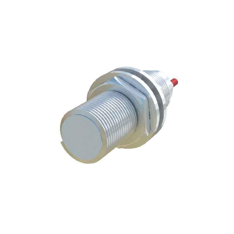
The receiver circuit is more nuanced. Connect the phototransistor's collector to the power supply via a pull-up resistor (values between 10k to 100k ohms are common; start with 10k). The emitter connects to ground. The voltage at the collector node will vary based on the amount of reflected IR light hitting the base of the phototransistor. More light causes more current to flow, pulling the collector voltage closer to ground. This analog signal is often too subtle for direct digital interpretation. Therefore, feed this signal into the non-inverting input of an op-amp configured as a comparator. A potentiometer connected to the inverting input sets a reference voltage threshold. When the received signal voltage exceeds this threshold, the op-amp's output swings high, indicating an object within the detection range.
Calibration is the most critical phase. Power the circuit in the environment where it will be used. Without any object in front of the sensor, adjust the potentiometer until the op-amp output just toggles low. This sets the baseline. Then, place a standard object (e.g., a white card) at the desired maximum detection distance (e.g., 10cm) and adjust the potentiometer again until the output toggles high. You may need to iterate this process and potentially adjust resistor values to achieve a stable and repeatable response. The detection range and sensitivity are influenced by the object's reflectivity, color, and the ambient IR conditions. For more precise distance measurement, rather than a simple on/off output, you can sample the analog voltage from the phototransistor collector using an ADC pin on a microcontroller. This voltage can be mapped to distance through empirical testing and creating a lookup table or calibration curve.
For enhanced performance, consider these engineering tips. Always house the sensor in a dark, opaque enclosure to shield the receiver from stray light. A small aperture for the IR pair improves directionality. Adding a simple capacitor (e.g., 10µF) across the power supply pins decouples noise. If using a microcontroller, implement software filtering (e.g., moving average) on the ADC readings to smooth out signal jitter. For demanding applications, consider using a dedicated IC like the GP2Y0A21YK0F, which handles modulation, demodulation, and output of an analog voltage proportional to distance, though building from discrete components offers invaluable learning.
This project solidifies understanding of optoelectronics, analog signal conditioning, and noise rejection techniques. The constructed sensor can be integrated into robotics for obstacle avoidance, in industrial automation for object counting, or in touchless interfaces. The principles demonstrated here—modulation, threshold detection, and calibration—are directly applicable to a vast array of sensing technologies. Experiment with different component