Building a DIY laser measurement sensor is an engaging project that merges optics, electronics, and programming. This guide provides a detailed walkthrough for engineers and hobbyists aiming to construct a precise, cost-effective sensor for applications like distance measurement, object detection, or alignment. The core principle involves emitting a laser beam and analyzing its reflection to calculate distance, typically using time-of-flight (ToF) or triangulation methods. For DIY purposes, triangulation is often preferred due to its simplicity and lower cost.
To begin, gather essential components: a laser diode module (650nm red laser is common), a linear CMOS or CCD sensor (like those from old barcode scanners or a dedicated module like the TCD1304), a focusing lens, a microcontroller (Arduino Uno or STM32), and supporting electronics (resistors, capacitors, and voltage regulators). The laser diode should be modulated to improve accuracy and reduce ambient light interference—a simple PWM signal from the microcontroller can achieve this. The receiver side requires the lens to focus the reflected laser spot onto the linear sensor, which converts light intensity into electrical signals.

Circuit design is critical. Power the laser diode with a constant current source to maintain stable output, and interface the linear sensor with the microcontroller via digital pins or SPI/I2C. For signal processing, use an operational amplifier to condition the sensor's analog output before feeding it to the microcontroller's ADC. Noise reduction techniques, such as adding a low-pass filter and shielding cables, are essential for reliable readings. Programming the microcontroller involves calibrating the sensor by mapping pixel positions to known distances. Implement algorithms to detect the laser spot's peak intensity on the sensor array; triangulation geometry then calculates distance based on the spot's displacement.
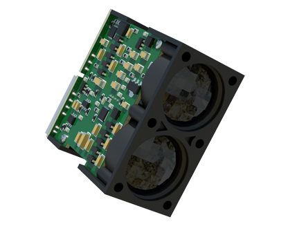
Calibration requires a test setup with reference targets at fixed distances. Record sensor readings and apply linear regression or lookup tables to derive a calibration curve. Factors like ambient temperature and surface reflectivity can affect accuracy, so consider implementing software compensation. For enhanced functionality, integrate features like data logging, wireless transmission (using Bluetooth or Wi-Fi modules), or a simple OLED display for real-time readings.
Potential challenges include alignment issues between the laser and sensor, which can be mitigated using adjustable mounts, and dealing with varying surface materials—matte surfaces scatter light, reducing signal strength. Always prioritize safety: wear laser safety goggles, avoid pointing the beam at eyes, and ensure the laser power complies with local regulations (Class 2 or lower is generally safe for DIY).
This project not only deepens understanding of photonics and embedded systems but also yields a versatile tool for robotics, home automation, or precision machining. With careful assembly and calibration, accuracy within ±1mm over a range of 0.5m to 2m is achievable. Experiment with different configurations, such as using infrared lasers for reduced visibility or incorporating multiple sensors for 3D scanning, to expand its applications. Remember, documentation and iterative testing are key to refining your DIY laser measurement sensor.