Voltage testing is a fundamental diagnostic procedure for proximity sensors, essential for verifying proper operation, troubleshooting failures, and ensuring system integrity. As a proximity sensor converts the presence or absence of a target into an electrical signal, its voltage characteristics at various points provide critical insights into its health and functionality. This guide outlines a systematic, industry-standard approach to testing voltage on both DC-powered inductive and capacitive proximity sensors, which are prevalent in industrial automation.
Safety First and Preliminary Checks
Before applying any test probes, adhere to all lockout/tagout (LOTO) procedures to isolate the sensor circuit from power. Confirm the sensor's specifications from its datasheet or nameplate: the supply voltage (e.g., 10-30 VDC), output type (PNP sourcing, NPN sinking, or analog), and whether it is normally open (NO) or normally closed (NC). Visually inspect the sensor, its connector, and wiring for any obvious damage, corrosion, or loose connections. Ensure the correct target material (ferrous for inductive, various for capacitive) and within the specified sensing range is available for testing.
Required Equipment
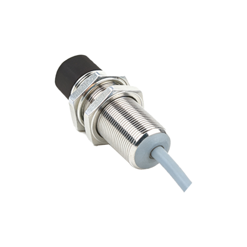
A digital multimeter (DMM) with DC voltage measurement capability is the primary tool. For dynamic switching tests, a DMM with a Min/Max or recording function is advantageous. Ensure you have the appropriate test leads and probes. A reliable DC power supply matching the sensor's rating is necessary if bench-testing.
Testing Procedure: Power Supply Voltage
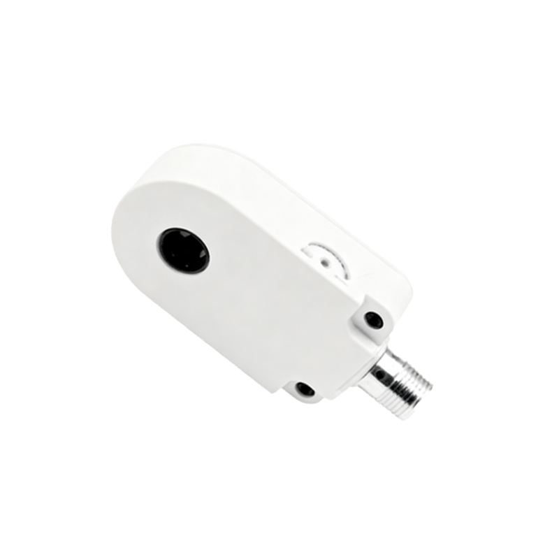
The first measurement is the supply voltage at the sensor's terminals. With power applied and the sensor in a stable state (target absent or present as per its normal condition), set your DMM to DC volts. Carefully probe between the positive supply line (typically brown wire for 3-wire DC sensors) and the negative/common line (typically blue wire). The reading should be within the specified range (e.g., 24 VDC ±10%). A voltage significantly lower than expected indicates a problem upstream, such as an overloaded power supply, excessive voltage drop due to long wire runs, or a short circuit.
Testing Procedure: Output Voltage (Switching Sensors)
For a 3-wire DC PNP (sourcing) sensor, the output wire is usually black. In its inactive state (no target detected for a NO sensor), the output transistor is off. Measure voltage between the black output wire and the blue common wire. A properly functioning sensor should show a very low "leakage" voltage, typically less than 1-2 VDC. When a valid target is brought within the sensing range, the output transistor switches on, connecting the output internally to the positive supply. The voltage measured between the output and common should now be very close to the supply voltage (e.g., ~24 VDC). For an NPN (sinking) sensor, the output sinks current to common. When inactive, the voltage between the output (usually black) and positive supply should be near supply voltage. When active, it should drop to a low voltage (near 0 VDC). Testing a 2-wire AC/DC sensor requires measuring the voltage drop across the sensor itself in its on and off states, which should be minimal when on and nearly full supply voltage when off.
Testing Procedure: Analog Output Voltage
For analog output sensors (e.g., 0-10 VDC), testing involves measuring the output voltage relative to common across the target's full range of motion. Without a target, the output should be at its specified offset (often 0V or a defined low value). As the target approaches, the voltage should increase smoothly and linearly (or according to its programmed characteristic) to its full-scale value (e.g., 10 VDC) at the nominal sensing point. Any nonlinearity, instability, or failure to reach the full-scale voltage indicates a potential sensor or scaling issue.
Troubleshooting Common Voltage Anomalies
No Output Voltage Change: Confirmed sensor is powered, target is correct and in range, but output voltage does not switch. Check if the load (e.g., PLC input, relay coil) is connected and functional. A disconnected load can sometimes prevent proper reading. Verify the sensor's output is not short-circuited.
Incorrect Output Voltage Level: Output only reaches a fraction of the supply voltage (e.g., only 12 VDC when supply is 24 VDC). This often points to an overloaded output or a failing output transistor. Measure the current draw of the load connected to the sensor.
Unstable or Fluctuating Voltage: This can be caused by electrical noise, a marginal power supply, a vibrating target, or a failing sensor. Try using a shielded cable, checking grounding, and using an oscill