In the rapidly evolving landscape of industrial automation and precision measurement, laser sensors have emerged as critical components for tasks ranging from object detection and distance measurement to alignment and quality control. For electrical engineers and prototyping enthusiasts, the Arduino platform provides a versatile and accessible gateway to integrating these sophisticated devices into functional systems. This guide delves into the practical aspects of programming laser sensors with Arduino, focusing on common interfaces, code structure, and real-world application considerations.
Laser sensors interfaced with Arduino typically communicate via digital, analog, or serial protocols. A common entry-point is the use of a simple digital laser module, often paired with a separate photoresistor or photodiode receiver. The programming logic here is straightforward: the Arduino digitally triggers the laser emitter, and the receiver's state is read to detect the presence or absence of an interrupting object. This forms the basis for basic tripwires or counters. For instance, adigitalRead() function on the receiver pin can signal a break in the beam. However, ambient light interference is a significant challenge with this method, necessitating careful calibration and sometimes modulation techniques in code to distinguish the laser signal from background noise.
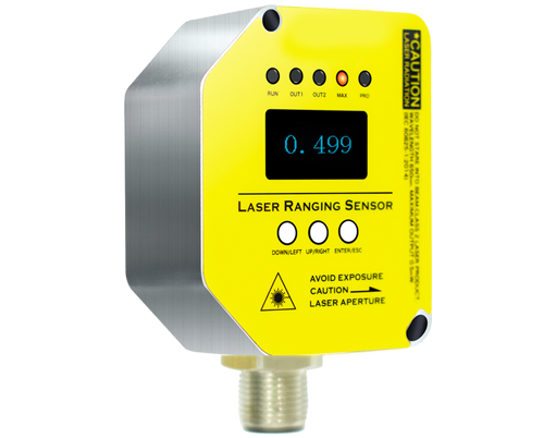
More advanced laser distance sensors, such as those based on Time-of-Flight (ToF) or triangulation principles, often use serial communication like UART (TX/RX) or I2C. These sensors handle the complex measurement internally and provide processed data to the Arduino. Programming these involves initializing the correct serial port and parsing the incoming data packet according to the manufacturer's datasheet. For an I2C device like a VL53L0X ToF laser sensor, the process includes including the relevant library (e.g.,Adafruit_VL53L0X), initializing the sensor object insetup(), and calling arangingTest() method inloop() to obtain a distance value in millimeters. The code must manage potential I2C address conflicts if multiple sensors are used and implement error-handling for out-of-range or failed readings.
A critical part of the program structure is thesetup() function. Here, engineers must correctly establish the communication protocol. For UART, this involvesSerial.begin(baud_rate) for the main debug port andSerial1.begin(baud_rate) for a dedicated hardware serial port connected to the sensor. For I2C,Wire.begin() is essential. Pin modes for power enable lines or trigger inputs must also be defined here. Neglecting proper initialization is a frequent source of failure.
The core measurement logic resides in theloop() function. Best practices dictate avoiding blocking code. Instead of usingdelay() to wait for measurements, a state machine or timestamp-based approach usingmillis() ensures the Arduino remains responsive. For example, one can structure the loop to check if a certain interval (e.g., 100ms) has passed since the last sensor query before reading it again. This is crucial in systems monitoring multiple inputs or controlling outputs concurrently. Data processing, such as running averages or median filters, should be applied to the raw sensor readings within the loop to smooth out noise and improve reliability before the values are used for decision-making.
Electrical engineers must also address hardware integration in their code. Laser sensors often require stable, clean power. The program can include sequences to power up the sensor gradually or check a "ready" pin status before initiating communication. Electromagnetic interference (EMI) from motors or relays can corrupt serial data; implementing software checksums (if not hardware-supported) and data validation routines adds robustness. Furthermore, for safety, the code should include a method to disable the laser output via a digital pin when not in active measurement, aligning with laser safety standards.
Consider a practical application: a precision positioning system using a laser distance sensor. The Arduino code would not only acquire distance but also implement a PID control algorithm based on the error between the measured and target distance. The output would adjust a servo or linear actuator. Such a program blends sensor polling, real-time calculation, and actuation control, demonstrating the Arduino's capability as a system controller. Debugging via the Serial Monitor, by printing sensor readings and status variables, is an indispensable part of the development workflow.

In conclusion, programming laser sensors with Arduino bridges high-precision sensing with flexible microcontroller logic. Success hinges on understanding the sensor's communication protocol, writing non-blocking, efficient code, and implementing rigorous data filtering and error handling. By mastering these aspects, electrical engineers can effectively prototype and deploy sophisticated laser-based systems for a wide array of industrial and research applications, leveraging the simplicity of the Arduino ecosystem to interface with complex electro-optical components.