In industrial automation and machinery monitoring, accurately measuring rotational speed is a fundamental requirement for ensuring operational efficiency, safety, and predictive maintenance. Among the various sensing technologies available, proximity switch sensors stand out for their reliability, non-contact operation, and robustness in harsh environments. This article delves into the principles, methodologies, and best practices for using inductive and capacitive proximity sensors to measure RPM (Revolutions Per Minute) and angular velocity.
The core principle behind using a proximity sensor for speed measurement is simple: detect the passage of a target object attached to a rotating shaft and convert the frequency of these detection events into a rotational speed value. Inductive proximity sensors are the most common choice for metallic targets. They generate an electromagnetic field; when a ferrous or non-ferrous metal target enters this field, it causes a change in oscillation amplitude, triggering the sensor's output switch. For non-metallic targets, such as plastic or liquid containers, capacitive proximity sensors, which detect changes in capacitance, are employed.
A typical setup involves mounting the proximity sensor in a fixed position, close to but not touching the rotating element. A single or multiple targets, often in the form of a gear, a keyway, a bolt head, or a dedicated tab on a coupling, are fixed to the shaft. Each time a target passes the sensor's face, it generates a pulse on the sensor's output line (PNP or NMP transistor output). This pulse train is the raw signal for speed calculation.

The critical step is processing this digital pulse signal. The most common method is frequency measurement. The rotational speed (N) in RPM is calculated using the formula: N = (f 60) / n, where 'f' is the frequency of pulses in Hertz (pulses per second), and 'n' is the number of targets per revolution. For a single target (n=1), the formula simplifies to RPM = f 60. For instance, if a shaft with one target generates a pulse frequency of 50 Hz, its rotational speed is 50 60 = 3000 RPM.
This pulse signal is typically fed into a programmable logic controller (PLC), a frequency counter, a tachometer module, or a dedicated data acquisition (DAQ) system. Modern PLCs have high-speed counter (HSC) input modules specifically designed for this purpose. The HSC counts the pulses over a precise time window (e.g., one second) set by the internal timer, and the PLC program executes the RPM calculation. For higher precision at lower speeds, a period measurement method can be used, where the time between two consecutive pulses is measured to calculate the instantaneous speed.
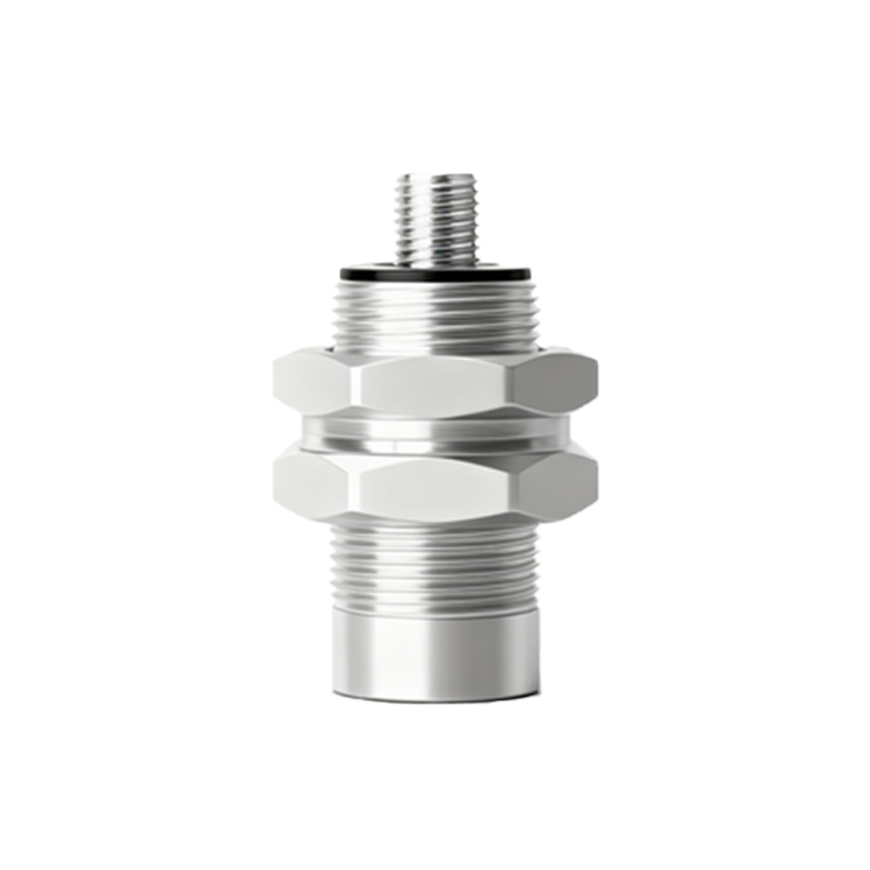
Several factors influence measurement accuracy and reliability. Sensor selection is paramount. Consider the sensing distance, target material and size, required switching frequency (which must be higher than the maximum pulse frequency), and environmental factors like temperature, humidity, and presence of contaminants. Proper mounting is crucial to avoid vibration-induced errors and ensure consistent detection. The target should be large enough to reliably actuate the sensor and should be positioned to provide a clean, sharp signal transition. Electrical noise in industrial settings can interfere with the pulse signal. Using shielded cables, proper grounding, and noise-immune sensor models is essential. For very high-speed applications, ensure the sensor's response time and the controller's input sampling rate are sufficiently fast to capture every pulse.
Beyond simple RPM readouts, this data is invaluable for system control and diagnostics. It can be used for overspeed/underspeed trip protection, closed-loop speed control of motors, synchronizing multiple drives, and trending vibration analysis. A sudden change in speed or the presence of irregular pulses can indicate issues like belt slippage, bearing wear, or imbalance.
In conclusion, proximity switch sensors offer a versatile and cost-effective solution for rotational speed measurement. By understanding the underlying principles, carefully selecting and installing the hardware, and implementing robust signal processing logic, engineers can achieve highly accurate and reliable speed monitoring. This capability forms the backbone of modern industrial condition monitoring and automated control systems, driving productivity and preventing costly downtime.