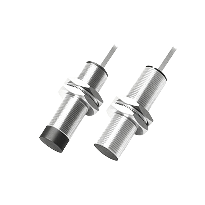
In industrial automation and control systems, proximity sensors are indispensable components for non-contact detection of metallic or non-metallic objects. Among the various mechanical and electrical specifications, thread dimensions play a critical role in ensuring proper installation, sealing, and performance. This article delves into the key thread specifications for proximity sensors, covering standards, selection criteria, and practical considerations for engineers.
Thread specifications for proximity sensors are primarily defined by international standards, with metric (M) and PG (Panzergewinde) threads being the most prevalent. Metric threads, such as M8, M12, M18, and M30, are widely adopted in global markets due to their standardization under ISO 1502 and IEC 61131-2. These threads feature a 60-degree flank angle and are designated by nominal diameter and pitch (e.g., M12x1.5). PG threads, common in European applications, include PG7, PG9, PG13.5, and PG16.5, characterized by a 80-degree flank angle and used often for cable gland integration. Additionally, NPT (National Pipe Taper) threads, like 1/8" NPT or 1/4" NPT, are utilized in North America for applications requiring a tapered seal against fluids or dust.
Selecting the correct thread specification involves multiple factors. First, the mounting environment dictates the thread type: cylindrical threads (e.g., metric) are suitable for through-hole mounting in control panels, while tapered threads (e.g., NPT) excel in harsh conditions where sealing is paramount. Engineers must verify the thread size against the sensor's housing diameter and the installation hole dimensions. For instance, an M12 sensor typically requires a 12mm hole with a 1.5mm pitch, but tolerances per ISO 965-1 ensure compatibility. Second, material compatibility is crucial—brass or stainless steel threads offer corrosion resistance in humid or chemical-laden settings, whereas plated steel may suffice for dry indoor use. Third, sealing requirements influence thread choice: many sensors integrate O-rings or washers (e.g., IP67-rated) with metric threads, while NPT threads inherently provide a tighter seal via thread engagement.
Practical installation tips can prevent common pitfalls. Always use a thread gauge to confirm pitch and diameter before mounting, as mismatched threads can damage the sensor or compromise sealing. For metric threads, apply a controlled torque (e.g., 10-15 Nm for M18) to avoid over-tightening, which may crack the housing. In high-vibration environments, consider locknuts or thread-locking adhesives to maintain sensor alignment. When integrating PG-threaded sensors with cable glands, ensure the gland rating matches the sensor's IP (Ingress Protection) class. For NPT threads, apply thread seal tape or compound sparingly to prevent contamination of the sensing face.
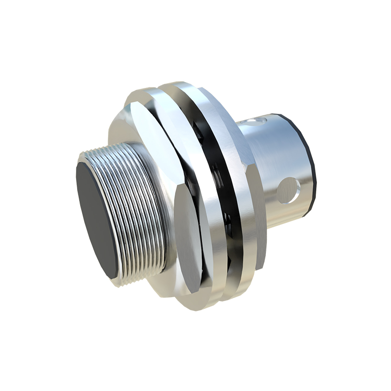
Beyond standard threads, custom specifications are emerging with Industry 4.0 trends. Some sensors now feature M12x1 connectors with 4-pin coding for quick-disconnect in IO-Link systems, blending electrical and mechanical functions. Additionally, miniaturized sensors (e.g., M5 threads) are gaining traction in robotics, where space constraints demand compact designs. Engineers should consult manufacturer datasheets for non-standard threads, as variations in pitch or flank angle can affect interchangeability.
In summary, proximity sensor thread specifications are not mere mechanical details but integral to system reliability. By adhering to international standards, assessing environmental needs, and following best practices, engineers can optimize sensor performance and longevity. As automation evolves, staying informed about thread innovations will ensure seamless integration in diverse industrial applications.