Proximity sensors are fundamental components in modern industrial automation, serving as the critical "eyes" of machinery for detecting the presence or absence of objects without physical contact. Their reliable operation hinges on correct assembly and installation. This guide details the essential methods and best practices for assembling proximity sensors, ensuring optimal performance and longevity in demanding electrical and industrial environments.
The assembly process begins long before physical mounting. A thorough pre-assembly checklist is paramount. First, verify the sensor type—inductive, capacitive, or photoelectric—against the application requirements. Inductive sensors detect metals, capacitive sensors detect both metals and non-metals, and photoelectric sensors use light beams. Selecting the wrong type is a primary cause of failure. Next, confirm the sensor's specifications: operating voltage (e.g., 10-30V DC, 20-250V AC), output type (PNP/NPN, NO/NC), sensing distance, and housing material (e.g., nickel-plated brass, stainless steel for harsh conditions). Ensure the electrical characteristics match your control system. Finally, inspect the sensor for any physical damage from shipping.
The core of assembly is mechanical mounting. The mounting style—threaded barrel, rectangular block, or ring-shaped—dictates the approach. For ubiquitous threaded barrel sensors (e.g., M8, M12, M18, M30), follow these steps:
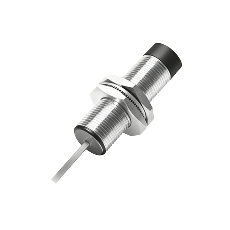
1. Drilling and Tapping: Create a mounting hole with the exact diameter and thread pitch specified. For metallic enclosures, use a tap to cut precise threads. Ensure the hole is clean and free of burrs to prevent housing damage and misalignment.
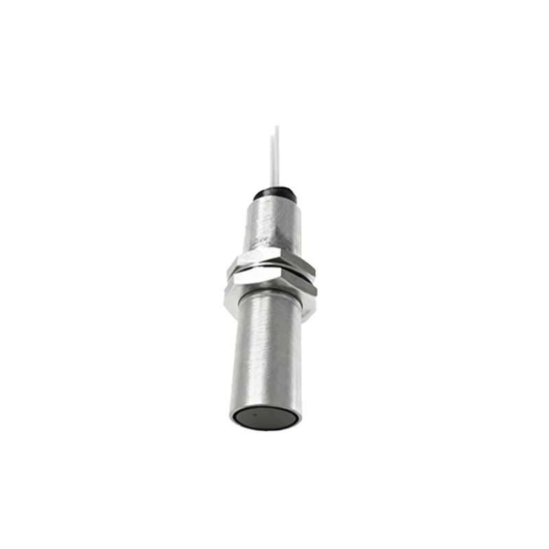
2. Sensor Insertion: Hand-tighten the sensor into the prepared hole. Avoid using tools on the sensor housing initially to prevent cross-threading or crushing the housing. The sensor should screw in smoothly.
3. Wrench Tightening: Once hand-tight, use an appropriate open-ended or box wrench on the integrated hex nut section of the sensor. Apply firm, even torque. Over-tightening can deform the housing, damage internal components, or alter the sensing field. Under-tightening may lead to vibration-induced loosening. Refer to the datasheet for recommended torque values, typically ranging from 5 to 20 Nm depending on size.
4. Orientation and Alignment: For optimal performance, ensure the sensing face is perpendicular to the expected path of the target object. Maintain the specified lateral and axial clearance from surrounding metal objects (usually 1-2 times the sensor diameter) to prevent false triggering from adjacent structures.
For rectangular or block-style sensors, use the provided mounting brackets or slots. Secure with the correct size of screws, often M4 or M5, and ensure the sensor is rigidly fixed without distorting its casing.
Electrical wiring is the next critical phase. Always disconnect power before making connections.
1. Cable Preparation: If using a pre-wired sensor, route the cable through a strain relief or cable gland to absorb mechanical stress. For sensors with quick-disconnect (QD) connectors, ensure the connector is securely mated and locked.
2. Connecting to the Circuit: Identify the wires: typically, brown (or red) for DC+, blue (or black) for DC- (or 0V), and black (or white) for the output signal. For AC sensors, wires may be brown (Live), blue (Neutral), and black (Output). Connect these to the corresponding power supply and load (e.g., PLC input, relay coil). Adhere strictly to the wiring diagram in the manual.
3. Shielding and Protection: In environments with significant electromagnetic interference (EMI) from motors or welders, use shielded cables. Ground the shield at the control panel end only. For long cable runs, consider conduit for physical protection.
4. Polarity Check: Double-check all connections, especially for DC sensors, as reverse polarity can instantly destroy the internal circuitry.
Following mechanical and electrical assembly, calibration and testing are mandatory.
1. Power Application: Apply the correct voltage. An indicator LED (usually on the sensor body) should illuminate, signaling power is present.
2. Sensing Adjustment: Some capacitive sensors have a potentiometer for sensitivity adjustment. Introduce the target material and adjust until detection is reliable without sensing background objects.
3. Distance Verification: Using the specified standard target (often a square of mild steel), verify the actual sensing distance. It should be within the rated nominal range. Account for factors like target material, size, and temperature, which can affect the sensing distance.
4. Functional Test: Cycle the target object in and out of the sensing field repeatedly. Monitor the sensor's output with a multimeter or PLC input indicator