Building your own proximity sensor at home is an engaging and educational project that combines electronics, programming, and practical application. A proximity sensor detects the presence or absence of an object within a certain range without physical contact, commonly used in devices like smartphones, robotics, and security systems. This guide will walk you through creating a simple infrared (IR) proximity sensor, a popular and accessible option for DIY enthusiasts.
To begin, you will need a few basic components: an IR LED, an IR photodiode or phototransistor, a suitable resistor (typically 220 ohms for the LED and 10k ohms for the photodiode), a breadboard, jumper wires, and an Arduino or similar microcontroller for processing signals. Optionally, you can include a buzzer or LED for output indication. Ensure you have a power source, such as a 5V USB connection or a 9V battery with a regulator.
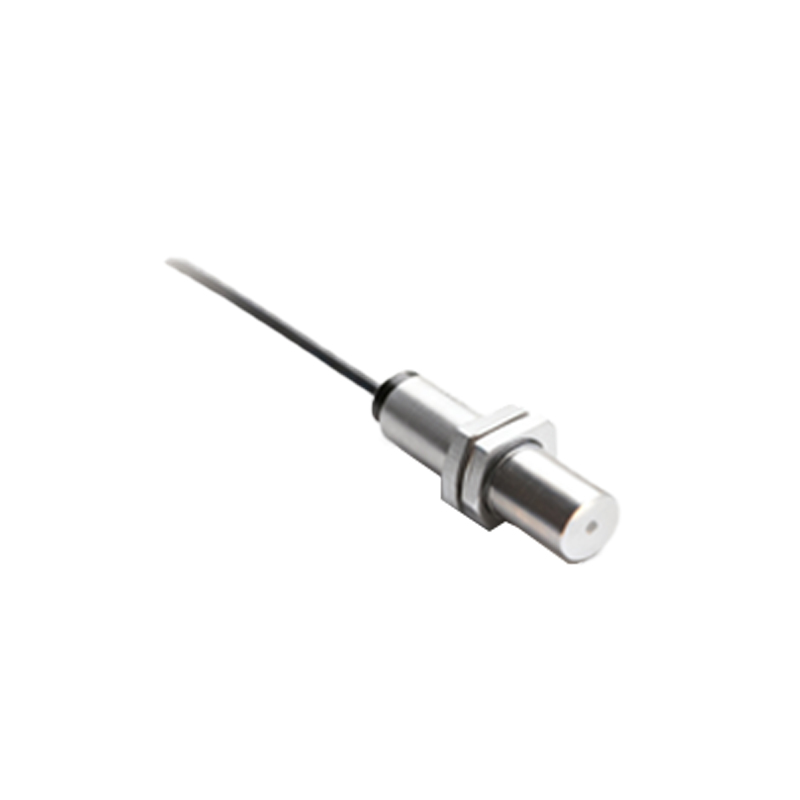
Start by setting up the hardware. Connect the IR LED to the breadboard, linking its anode (longer leg) to a digital pin on the Arduino through the 220-ohm resistor to limit current and prevent damage. Connect the cathode (shorter leg) to ground. For the IR photodiode, place it on the breadboard near the IR LED but oriented to receive reflected light. Connect one end to power (5V) and the other to an analog pin on the Arduino via the 10k-ohm resistor, with the same end also connected to ground to form a voltage divider circuit. This setup allows the photodiode to detect IR light bounced back from an object, with the voltage changing based on proximity.
Next, focus on the software side. Write a simple code using the Arduino IDE. Initialize the IR LED pin as an output and the photodiode pin as an input. In the loop function, turn on the IR LED by setting its pin to HIGH, then read the analog value from the photodiode pin. This value will decrease as an object gets closer because more IR light is reflected onto the photodiode, altering the voltage. You can set a threshold value to determine when an object is detected—for example, if the reading falls below 500, trigger an output like lighting an LED or sounding a buzzer. Calibrate the sensor by testing with objects at different distances to fine-tune the threshold for reliable detection.
Testing and calibration are crucial steps. Power up your circuit and observe the serial monitor in the Arduino IDE to see the analog readings as you move an object toward the sensor. Adjust the threshold in the code based on these readings to achieve the desired sensitivity. Factors like ambient light and surface reflectivity can affect performance, so consider testing in various conditions. For better accuracy, you can shield the sensor from external light using a tube or enclosure, and ensure the IR LED and photodiode are closely aligned to optimize reflection detection.
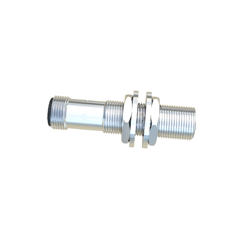
Once your basic sensor is working, you can explore enhancements. For instance, add multiple sensors for wider coverage, integrate it with a servo motor to create a tracking system, or connect it to a smartphone app via Bluetooth for remote monitoring. Applications are vast, from building a simple parking assistant for your garage to crafting interactive art installations. Always prioritize safety by double-checking connections, using appropriate resistors, and avoiding short circuits.
In summary, creating a DIY proximity sensor is a rewarding project that demystifies sensor technology. It encourages hands-on learning about electronic components, circuit design, and basic coding. With practice, you can adapt this knowledge to more complex projects, fostering innovation and problem-solving skills. Remember to document your process, share your results with online communities, and enjoy the journey of making technology tangible from the comfort of your home.