Magnetic proximity sensors are fundamental components in modern industrial automation, offering non-contact detection of ferrous and non-ferrous metallic objects. These devices operate based on distinct physical principles, primarily categorized into inductive and capacitive types. Understanding the underlying mechanisms of capacitance and inductance within these sensors is crucial for engineers to select, implement, and troubleshoot them effectively in diverse applications, from assembly lines to safety systems.
Inductive proximity sensors are the most common type for detecting metallic objects. Their operation hinges on the principle of electromagnetic induction. The core component is a coil wound around a ferrite core, which forms an oscillator circuit. When an alternating current passes through this coil, it generates a high-frequency electromagnetic field at the active face of the sensor. In the absence of a target, this oscillator operates at a constant amplitude. When a conductive metal object enters this oscillating field, eddy currents are induced on the surface of the target. These eddy currents draw energy from the oscillator, causing a reduction in its amplitude. The sensor's internal circuitry monitors this amplitude change. Once the amplitude drops below a predefined threshold, the output state of the sensor switches, signaling the presence of the target. The effective sensing distance depends on factors like the target's material, size, and shape. Ferrous metals (like iron and steel) typically induce stronger eddy currents and can be detected from a greater distance compared to non-ferrous metals (like aluminum or copper) due to their higher permeability. The term "inductance" here refers to the property of the coil; the presence of the metallic target effectively alters the coil's inductance, which is the parameter the detection circuit ultimately responds to.
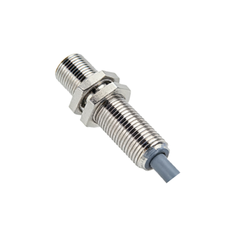
Capacitive proximity sensors, while sometimes used for metals, excel at detecting a much wider range of materials, including liquids, plastics, glass, and wood. They function based on the principle of capacitance change. A capacitive sensor essentially forms one plate of a capacitor, with the target object acting as the other plate, and the intervening space as the dielectric. The sensor's active face contains a metallic electrode connected to an oscillator circuit. This electrode generates a low-power electrostatic field. When any material with a dielectric constant different from air enters this field, it alters the capacitance of the system. Even non-conductive materials have a dielectric constant higher than air (which is approximately 1). This increase in capacitance changes the oscillation characteristics. Similar to the inductive type, the circuit detects this change—often a frequency shift—and triggers an output switch when it exceeds a set level. For conductive materials like metals, the effect is more pronounced as they act as an excellent second plate, significantly increasing the capacitance. A key advantage is the ability to adjust the sensitivity, often via a potentiometer, to tune out unwanted background materials or to detect specific substances through containers.
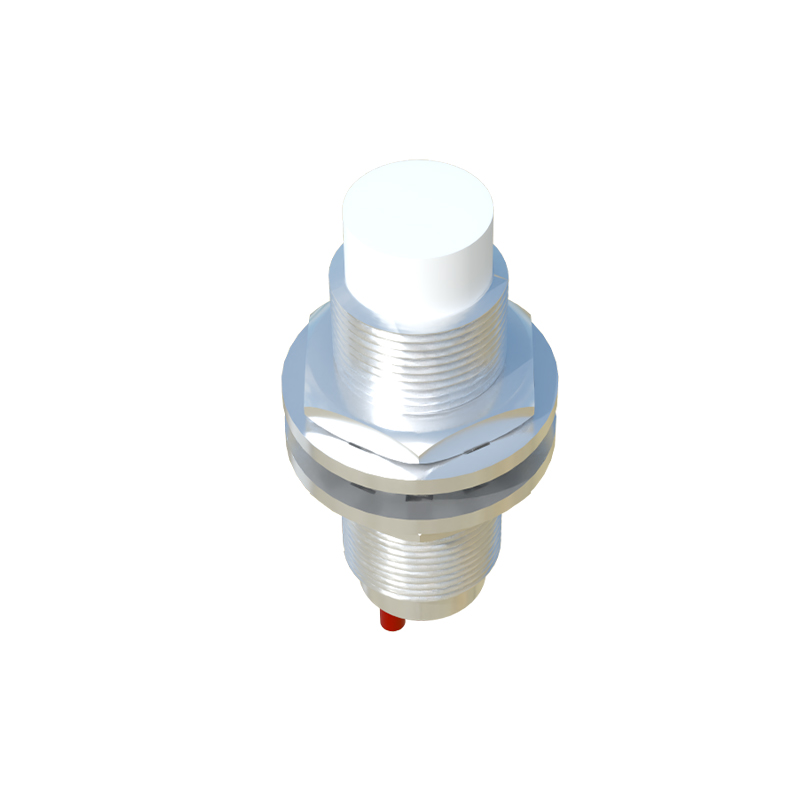
The distinction in their operating principles leads to clear application differences. Inductive sensors are highly reliable for metal detection in harsh industrial environments. They are largely immune to dust, dirt, and moisture (unless submersed) and do not react to non-metallic substances. They are ideal for counting metal parts, determining position limits, or monitoring rotational speed. Capacitive sensors are more versatile but also more susceptible to environmental interference. Changes in humidity, temperature, or the presence of condensation can affect the dielectric constant and lead to false triggering. Therefore, they are perfectly suited for applications like liquid level sensing in tanks, detecting filled vs. empty bottles on a conveyor, or monitoring the presence of granular materials in hoppers. Engineers must consider the target material, environmental conditions, required sensing distance, and response frequency when choosing between the two.
From a circuit design perspective, both sensor types integrate sophisticated electronics to translate the physical phenomenon (inductance or capacitance change) into a clean, usable digital or analog output. Modern sensors include features like short-circuit protection, overload protection, and immunity to electrical noise. The choice between PNP (sourcing) and NPN (sinking) output configurations is another critical decision based on the control system's PLC or controller input type.
In summary, magnetic proximity sensors, through their inductive and capacitive variants, provide essential eyes for automated systems. Inductive sensors, leveraging changes in coil inductance due to eddy currents, offer robust metal-only detection. Capacitive sensors, operating on shifts in system capacitance, deliver material-agnostic detection capabilities at the cost of greater environmental sensitivity. A deep comprehension of these capacitance and inductance principles empowers engineers to deploy these sensors with precision, ensuring reliability, efficiency, and safety in complex industrial operations. Continuous advancements in miniaturization, sensing range, and integrated diagnostics are further expanding their roles in the evolving landscape of Industry 4.0 and smart manufacturing.