In industrial automation and control systems, proximity switch sensors are indispensable components for non-contact detection of objects. Their reliable operation hinges significantly on a stable and appropriate power supply. This article delves into the critical aspects of powering proximity sensors, addressing common challenges and providing practical guidelines for engineers and system integrators.
Proximity sensors, including inductive, capacitive, and photoelectric types, typically operate on low-voltage DC power. The most common supply voltages are 10-30 VDC, with 12 VDC and 24 VDC being industry standards. Selecting the correct voltage is paramount. Operating a 12 VDC sensor on a 24 VDC line will almost certainly cause permanent damage due to overvoltage, while underpowering it with a lower voltage leads to unreliable switching or complete failure to operate. Always consult the manufacturer's datasheet for the specified operating voltage range (e.g., 10-30 VDC) and ensure the power supply complies.
Beyond voltage, current capacity (amperage) is crucial. The power supply must deliver sufficient current to handle the total load of all connected sensors plus a safety margin. Each sensor draws a quiescent current (when inactive) and, for certain types like sinking or sourcing DC sensors, a load current through the output circuit. Calculate the total current draw by summing the maximum current consumption of all sensors on the same supply line. A power supply rated at or above this total, typically with a 20-30% overhead, ensures stability and prevents voltage drops during simultaneous switching events.
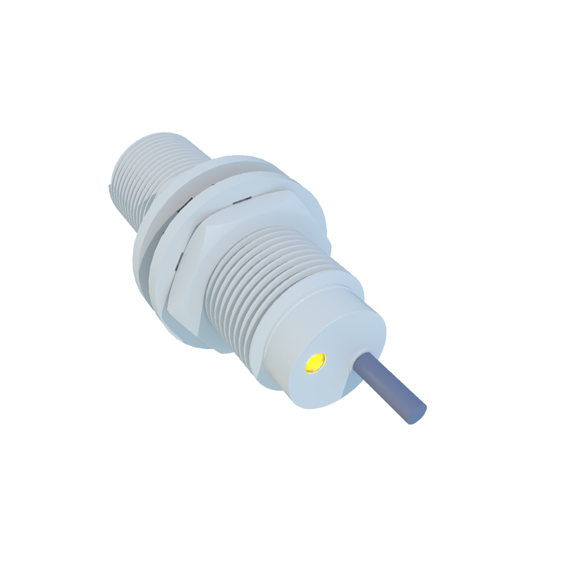
Electrical noise and interference are prevalent in industrial environments, generated by motors, variable frequency drives (VFDs), and welding equipment. This noise can induce false triggering or signal instability in sensitive proximity sensors. To mitigate this, use a regulated and filtered DC power supply designed for industrial use. Implementing proper grounding practices is non-negotiable: use a single-point ground for the power supply and sensor commons. Shielded cables, with the shield grounded only at the power supply end, are highly effective in rejecting electromagnetic interference (EMI). For extreme noise environments, consider installing ferrite cores on power cables or using isolated power supplies to break ground loops.
The type of sensor output influences power supply wiring. Three-wire DC sensors are most common, with separate wires for power supply positive (+Vs), power supply common (0V), and the output signal. In a sinking (NPN) configuration, the load is connected between the output and +Vs; the sensor switches the common (0V) to the load. In a sourcing (PNP) configuration, the load is connected between the output and common (0V); the sensor switches the +Vs to the load. The power supply common must be connected correctly to the system's common reference point. Two-wire AC/DC sensors simplify wiring by operating in series with the load but have higher leakage current and voltage drop considerations.
Voltage drops over long cable runs can be a significant issue. Using undersized wires creates resistance, leading to a reduced voltage at the sensor compared to the power supply output. This can cause erratic behavior. To minimize voltage drop, calculate the appropriate wire gauge based on the total current and cable length. For extensive systems, consider using a distributed power architecture with local power supplies or higher supply voltages (like 24 VDC) to compensate for the drop, ensuring the sensor still receives voltage within its operational window.
Protection against voltage transients, surges, and reverse polarity is essential for longevity. Incorporate protective devices such as fuses or circuit breakers on the power supply line. Transient voltage suppressors (TVS diodes) or surge protectors safeguard against voltage spikes from inductive load switching or lightning. Some sensors have built-in reverse polarity protection, but using a power supply with this feature or adding a series diode provides an extra layer of security, preventing damage from accidental incorrect wiring.
In summary, the power supply is not merely an accessory but the foundation of reliable proximity sensor performance. Key steps include matching voltage and current specifications, implementing robust noise suppression and grounding, understanding output wiring schemes, accounting for voltage drop in cabling, and integrating adequate circuit protection. A meticulous approach to power supply design prevents downtime, reduces maintenance costs, and ensures the precision required in modern automated industrial systems. Always prioritize using high-quality, industrial-grade power supplies and adhere strictly to the sensor manufacturer's installation guidelines.