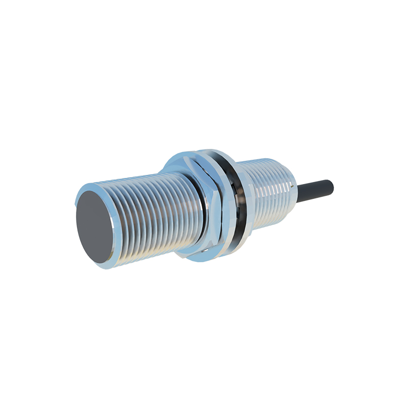
Cylindrical proximity sensors are ubiquitous in industrial automation, serving as the silent sentinels for object detection, positioning, and counting. Their robust, tubular metal housing makes them ideal for harsh environments. However, their reliability hinges on one critical factor: proper adjustment. Incorrect setup leads to false triggers, missed detections, and costly downtime. This guide provides a systematic, practical approach to adjusting these sensors for peak performance, ensuring your machinery operates smoothly and efficiently.
Before any adjustment, safety is paramount. Always lock out and tag out the machinery to prevent accidental activation. Consult the sensor's specific datasheet from the manufacturer. Key specifications to note are the sensing distance (Sn), hysteresis, and output type (PNP/NPN, NO/NC). The nominal sensing distance is a theoretical value under ideal conditions; the effective operating distance in practice is often less due to target material, size, and environmental factors.
The adjustment process begins with mechanical mounting. Ensure the sensor is securely fastened in its bracket. The sensing face must be parallel to the target object's approach path. For side-sensing models, the target should approach perpendicular to the sensor's axis. Avoid mounting multiple sensors too close together to prevent mutual interference. A general rule is to maintain a distance of at least twice the sensor diameter between adjacent units.
Next, focus on the target itself. The standard sensing distance is calibrated for a mild steel square target of a specified size (often equal to the sensor face diameter). If your target is a different material—such as aluminum, brass, stainless steel, or plastic—you must apply a correction factor. Non-ferrous metals typically reduce the effective range, while plastics may not be detectable by inductive sensors at all, requiring a capacitive type. Ensure the target is large enough and consistently presented to the sensing field.
Now, proceed to electrical connection and preliminary adjustment. Wire the sensor according to its output configuration (typically brown = +V, blue = 0V, black = output) and your controller's input requirements. Many cylindrical sensors feature a built-in LED indicator that lights up when an object is detected. This LED is your primary tool for adjustment. Power the system and manually bring the standard target toward the sensing face along the correct axis.
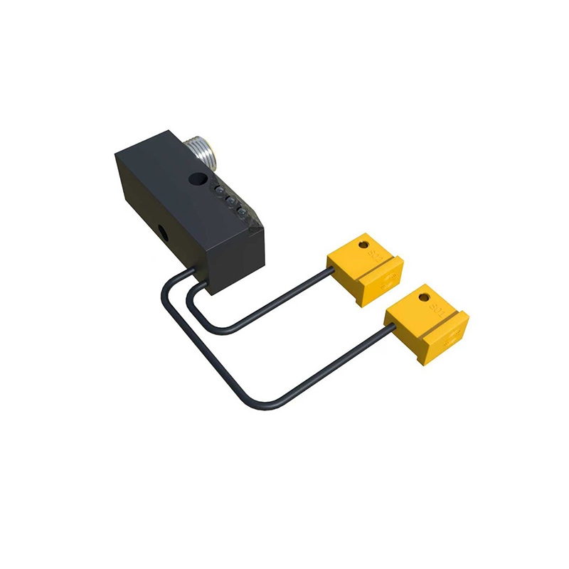
Observe the indicator LED. The point where the LED first turns on is the "operate point." Slowly retract the target. The point where the LED turns off is the "release point." The difference between these two points is the sensor's hysteresis. This built-in dead band prevents chatter when a target is positioned at the exact sensing boundary. Do not attempt to eliminate it; it is a necessary feature.
Fine-tuning is where precision is achieved. Most industrial cylindrical proximity sensors have a potentiometer (a small screw) or teach-in function for adjusting sensitivity. Using a non-metallic screwdriver, turn the potentiometer slightly. Bring the target to the desired operational position—this should be closer than the maximum detected operate point to account for variations in target position, temperature drift, and voltage fluctuations. Adjust the potentiometer until the LED just turns on. Then, move the target slightly further away to ensure the LED turns off, confirming the hysteresis is active. This sets a reliable switching point with a safety margin.
For applications with varying target materials or demanding precision, use a setting gauge or shim of the correct material and thickness. Position it at the exact required sensing distance and adjust the potentiometer until the indicator triggers. This method removes guesswork.
After adjustment, rigorous testing is non-negotiable. Cycle the target through the detection zone at least 10-15 times at the normal operational speed. The sensor should consistently and reliably trigger each time. Test under real-world conditions, considering factors like vibration, temperature changes, and the presence of dust or moisture. Monitor for any erratic behavior or failure to detect.
Common pitfalls include ignoring the sensing field's shape. The field is not a sharp line but a 3D hemisphere or cylinder extending from the face. Be aware of possible interference from metal brackets, machine frames, or moving parts entering this field. Also, ensure the power supply voltage is stable and within the sensor's specified range, as low voltage can reduce sensing distance.
Finally, document your settings. Note the potentiometer position or the exact distance achieved with the specific target. This creates a valuable reference for future maintenance or troubleshooting.
By following this methodical process—prioritizing safety, understanding specifications, meticulous mechanical setup, careful electrical connection, precise sensitivity adjustment with the target in the operational position, and exhaustive real-world testing—you can master the adjustment of cylindrical proximity sensors. This ensures they deliver the unwavering reliability that modern automated systems demand, maximizing uptime and productivity.