Proximity sensors are essential components in modern industrial automation, providing non-contact detection of objects. When integrated with pneumatic systems, proper wiring and connection methods are critical to ensure reliable operation, safety, and longevity. This article outlines key pneumatic wiring techniques for inductive and capacitive proximity sensors commonly used in manufacturing and processing environments.
First, understanding the sensor type is fundamental. Inductive proximity sensors detect metallic objects, while capacitive sensors can detect both metallic and non-metallic materials. Most industrial proximity sensors operate on DC voltages (typically 10-30V DC) or AC voltages (90-250V AC), with three-wire configurations being the standard. The wiring process involves connecting the power supply, load (such as a pneumatic valve solenoid), and ground.
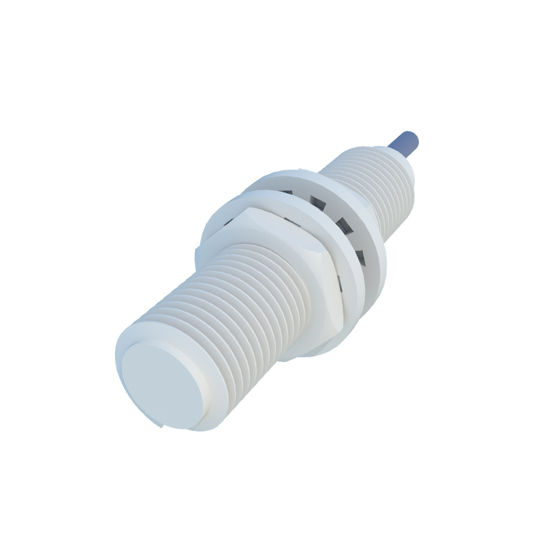
For DC sensors, the common wiring method includes:
1. Brown wire: Connect to the positive DC voltage supply.
2. Blue wire: Connect to the negative DC supply or ground.
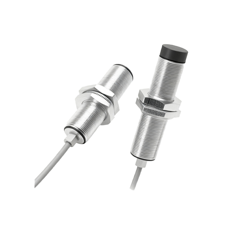
3. Black wire: This is the output wire, which should be connected to the pneumatic solenoid valve's control input. When an object is detected, the output switches, allowing current to flow to the solenoid, activating the pneumatic valve.
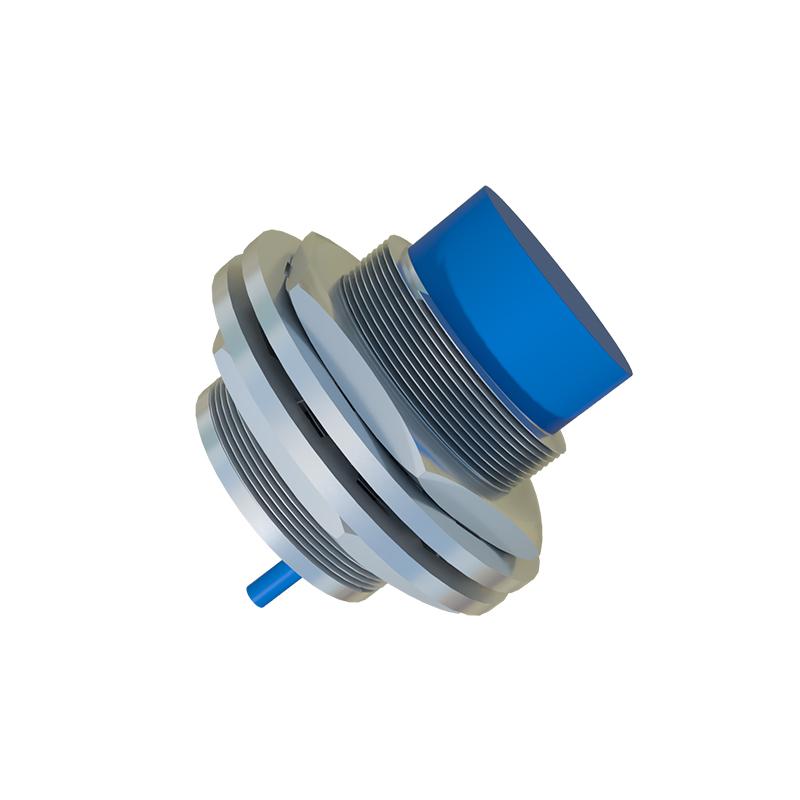
In AC-powered sensors, wiring typically follows:
1. Brown wire: Connect to the phase (hot) AC line.
2. Blue wire: Connect to the neutral AC line.
3. Black wire: Connect to the load. Ensure the solenoid valve is rated for the same AC voltage to prevent damage.
Pneumatic integration requires attention to solenoid valve specifications. The sensor output must match the valve's coil voltage and current requirements. Using a relay or interface module is advisable if the sensor output current is insufficient to drive the solenoid directly. This protects both the sensor and valve from overload.
Shielding and grounding are vital for noise immunity, especially in environments with motors or frequency drives. Use shielded cables, and connect the shield to ground at one end only to avoid ground loops. Keep sensor cables away from high-voltage power lines to reduce electromagnetic interference.
Conduit and cable management should comply with industrial standards like NEC or IEC. Use waterproof connectors (IP67 or higher) if sensors are exposed to moisture, dust, or chemicals. For pneumatic systems, ensure tubing is securely attached and does not interfere with electrical wiring.
Testing and maintenance involve verifying sensor operation with a target object before full system integration. Check for stable output signals using a multimeter or oscilloscope. Regularly inspect connections for corrosion or looseness, which can cause intermittent failures in pneumatic actuation.
In summary, proper pneumatic wiring for proximity sensors involves correct voltage matching, adequate shielding, and adherence to safety codes. These practices minimize downtime and enhance system efficiency in automated industrial setups.